Methods for calefaction densifaction of a porous structure
Inactive Publication Date: 2004-02-05
COMMISSARIAT A LENERGIE ATOMIQUE ET AUX ENERGIES ALTERNATIVES
View PDF6 Cites 15 Cited by
Summary
Abstract
Description
Claims
Application Information
AI Technical Summary
This helps you quickly interpret patents by identifying the three key elements:
Problems solved by technology
Method used
Benefits of technology
Benefits of technology
[0012] The object of the present invention is precisely an improvement of the film-boiling densification methods for porous structures, which makes possible reducing the electrical power consumed and increasing the densification rate as well as improving the homogeneity of the texture of the deposited product in the case where it is carbon.
[0016] The reduction of the electrical energy is principally due to the fact that the vaporization of the precursor, which is a very endothermic phenomenon, absorbing energy and cooling the exterior of the porous structure, is greatly reduced in terms of flow.
[0018] Finally, in the case, wherein the method of the invention is used for densifying a porous structure by carbon deposition, the filter also improves, for the range of temperatures least elevated, homogeneity of the carbon deposited. It makes possible elimination of the formation of mosaic or ex-pitch type carbon at the interior of the strands or mesh of fibers of the porous structure, while attenuating or mollifying the perturbations due to boiling of the precursor, or the surge penetration of the liquid into the porous structure.
[0019] Thus, according to the invention, these results are achieved by reducing the flow of liquid precursor entering into the porous structure which is the opposite of the object pursued by the document [4], wherein, in contrast, the object is to increase the flow of precursor into the structure by the creation of liquid waves, rather than limiting them.
non-optimized densification rates, since the thermal gradients are very high and the densification rate diminishes as the thermal gradient increases.
Method used
Image
Click on the blue label to locate the original text in one second.
Reading with bidirectional positioning of images and text.
Examples
example 1
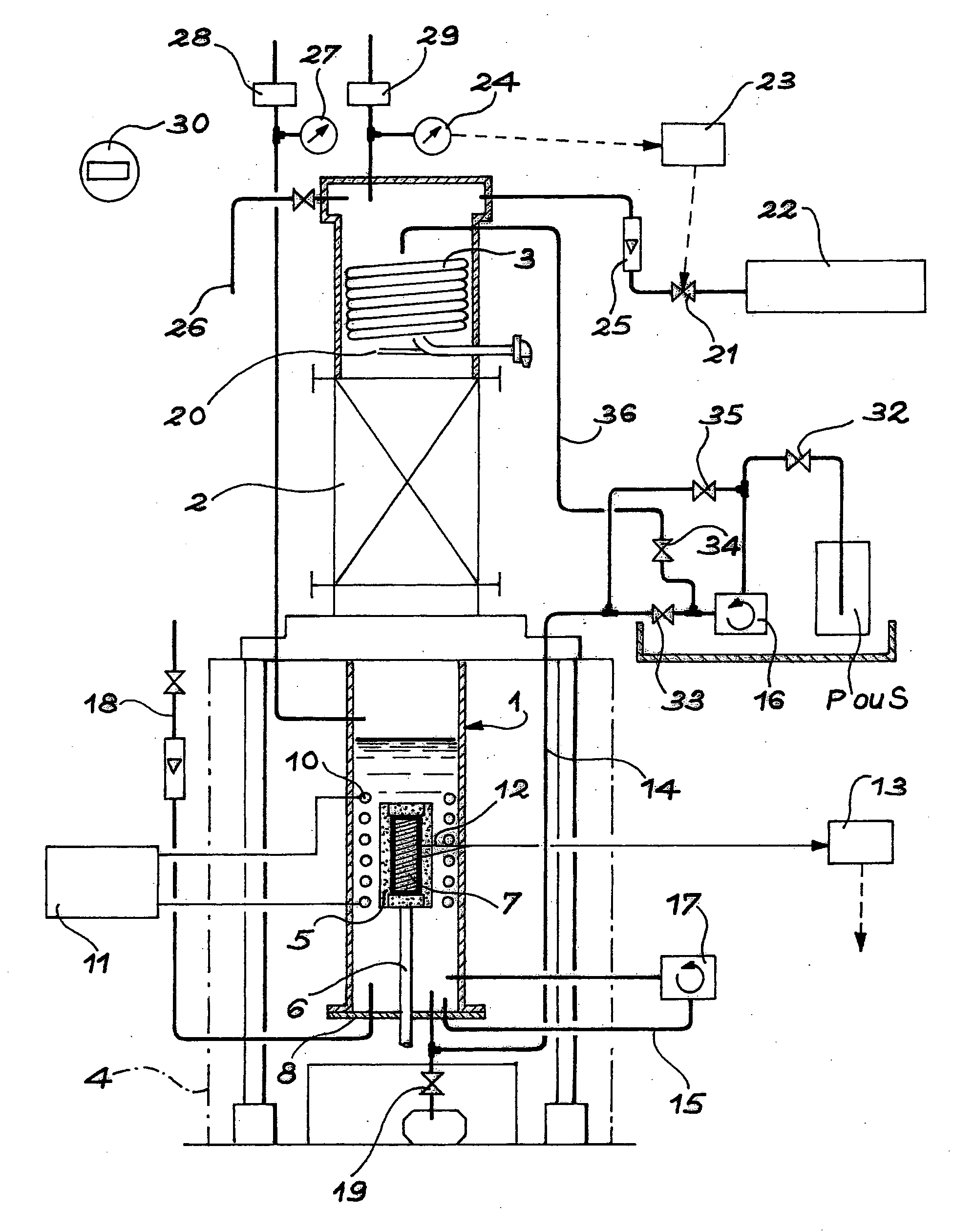
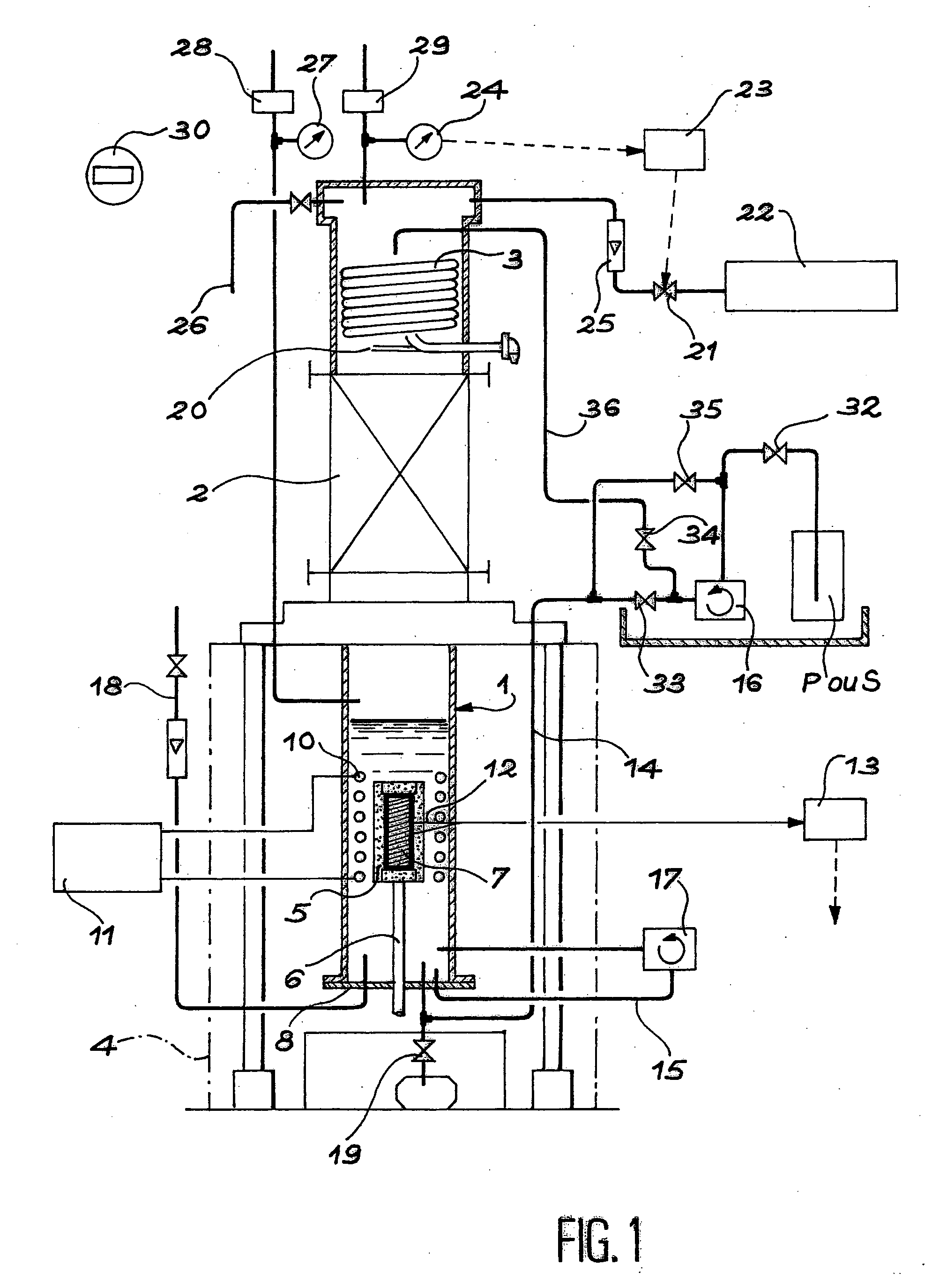
[0069] The reactor used has an inside diameter of 200 mm, an height of 300 mm. The inductor that is arranged inside the reactor, has a height of 150 mm and is comprised of six turns having inside and outside diameters having values of 175 mm and 195 mm, respectively.
[0070] The susceptor used has a diameter-of 80 mm and a height of 100 mm. It is entirely covered using three pieces of carbon felt (density 0.40 to 0.45) to be densified:
[0071] a hollow cylinder having inside and outside diameters, respectively, of 80 and 120 mm and a height of 100 mm, covering its lateral surface;
[0072] two disks having a diameter of 120 mm and a thickness of 20 mm covering the top and bottom parts of the two flat surfaces.
[0073] The system is covered with a filter formed of two layers of polytetrafluorethlylene GORE-TEX.RTM., having the following characteristics:
[0074] thickness of one layer 0.2 mm
[0075] filtration: allows passage only of particles of a diameter less than 7.5 .mu.m;
[0076] permeability:...
example 2
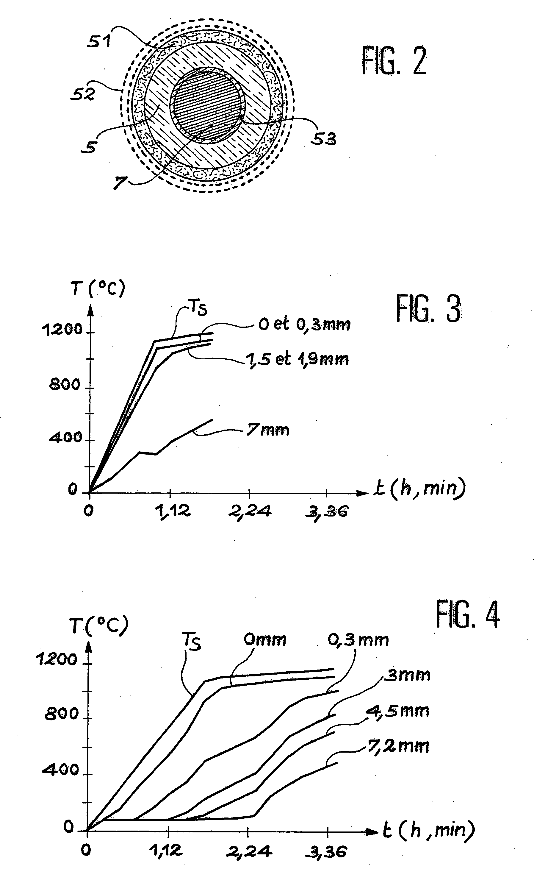
[0088] This example relates to the densification of small pieces of carbon. Heating is done resistively.
[0089] The heating element is a bar of graphite 3 mm in diameter. It is surrounded by the sample to be densified, which is a tube of carbon felt (density 0.1) 2 cm in diameter and 3 cm in height. The system is enveloped in a filter formed of two layers of GORE-TEX tissue, as in Example 1.
[0090] The pressure is set at 0.1 MPa. The temperature increase is done at a rate of 1,000.degree. C. / h up to 1,100.degree. C. The temperature is held at 1,100.degree. C. for 30 minutes, then lowered at a rate of 1,000.degree. C. / h.
[0091] The results are as follows
[0092] the rate of densification is 4 mm / h
[0093] the energy consumed is 110 kWh / kg of carbon deposited;
[0094] the density is 1.8.
[0095] By comparison, if there were no GORE-TEX.RTM. filter, under the same conditions
[0096] the rate of densification is 0.6 mm / h
[0097] the energy consumed is 1,400 kWh / kg of carbon deposited
[0098] the density...
PUM
Property
Measurement
Unit
Thickness
aaaaa
aaaaa
Thickness
aaaaa
aaaaa
Thickness
aaaaa
aaaaa
Abstract
The invention relates to a film-boiling densification method for a porous structure (mixed gas-liquid method) (5) consisting in immersing of the porous structure into a liquid precursor, a hydrocarbon, for example, and heating the system in order to deposit the decomposition product of said liquid precursor, for example carbon, into the pores of the porous structure, characterized in that the flow of the liquid precursor entering the porous structure is reduced, for example by means of a filter (52) made of polytetrafluorethylene surrounding the structure so as to reduce the vaporization phenomenon of the liquid precursor around the porous structure to be densified.
Description
[0001] The object of the present invention is a densification method for a porous structure and, more precisely, it relates to an improvement of said method, which makes possible reducing the electrical power consumed and increasing the densification rate as well as improving the homogeneity of the texture of the product deposited.[0002] It will be recalled that the film-boiling densification method (gas-liquid mixed method) for a porous structure consists in filling the spaces of the porous structure by depositing in same a material identical to or different from that comprising the structure, by thermal decomposition of a liquid precursor.[0003] The invention applies to the densification of a porous material, in particular felts, textiles, needle-punched and three-directional preforms, can be advantageously used because of their high mechanical resistance, their excellent thermal insulating ability, and their good resistance to shock and abrasion, for producing thermal shielding, ...
Claims
Application Information
Patent Timeline
Application Date:The date an application was filed.
Publication Date:The date a patent or application was officially published.
First Publication Date:The earliest publication date of a patent with the same application number.
Issue Date:Publication date of the patent grant document.
PCT Entry Date:The Entry date of PCT National Phase.
Estimated Expiry Date:The statutory expiry date of a patent right according to the Patent Law, and it is the longest term of protection that the patent right can achieve without the termination of the patent right due to other reasons(Term extension factor has been taken into account ).
Invalid Date:Actual expiry date is based on effective date or publication date of legal transaction data of invalid patent.

