Dental diagnostic and treatment apparatus

a technology for diagnosis and treatment, applied in the field of dental diagnosis and treatment equipment, can solve the problems of significant increase in cost, difficulty in observing the treatment area, and suffer the efficiency of treatment work, so as to confirm the extent and degree of treatment, work efficiency increases, and work efficiency thus increases

Inactive Publication Date: 2007-05-31
MORITA MFG CO LTD
View PDF8 Cites 69 Cited by
  • Summary
  • Abstract
  • Description
  • Claims
  • Application Information

AI Technical Summary

Benefits of technology

[0060] According to the present invention described above, since the light radiating unit including the light source for radiating the light for distinctively detecting a lesion onto the target area is provided near the diagnostic/treatment tool of the dental diagnostic and treatment apparatus, the clinician who is performing diagnosis or treatment using this dental diagnostic and treatment apparatus can clearly observe intraoral lesions such as caries, sclerotic dentin, tartar, plaque, biofilm, teeth chipping, cracking, etc. by visual examination using a filter or the like for detecting the reflected light or the fluorescence occurring due to excitation by the radiated light, and can thus confirm the extent and degree of the treatment while performing the diagnosis or treatment.
[0061] Further, by also installing a plurality of light emitting devices of different wavelengths or an illumination light source such as a white light source, it becomes possible to detect different kinds of lesions by switching the lesion detection function manually or in a time division fashion, or to illuminate lesions for visual examination. Since the clinician does not need to change the handpiece according to the kind of the lesion or the purpose of the diagnosis or treatment, the work efficiency increases.
[0062] Furthermore, since the light radiating unit for illuminating the target area can also be mounted near the diagnostic/treatment tool of the dental diagnostic and treatment apparatus, the clinician can perform the diagnosis or treatment by switching between the illumination device and the diagnostic/treatment device, and the work efficiency thus increases.
[0063] As described above, according to the present invention, when the intraoral illumination device ...

Problems solved by technology

However, depending on the orientation of the patient and the area to be treated or on the direction from which the clinician such as the dentist works, the oral cavity may not be illuminated sufficiently, making it difficult to observe the treatment area; every time this happens, the position of the shadow-free light has to be adjusted, and the efficiency of the treatment work thus suffers.
This requires the light guide to be formed in a special shape, resulting in a significant increase in cost.
Furthermore, the structure for accommodating the light guide of such shape within the handpiece body becomes complex, and the manufacturing cost increases.
There has also been the problem that the mechanism for holding the light exit end portion of the light guide interferes with the fundamental vibration of the scaler, causing an adverse effect on the vibration characteristics of the product.
However, with the technique disclosed in Patent Documen...

Method used


Image

  • Dental diagnostic and treatment apparatus
  • Dental diagnostic and treatment apparatus
  • Dental diagnostic and treatment apparatus

Examples


embodiment 1

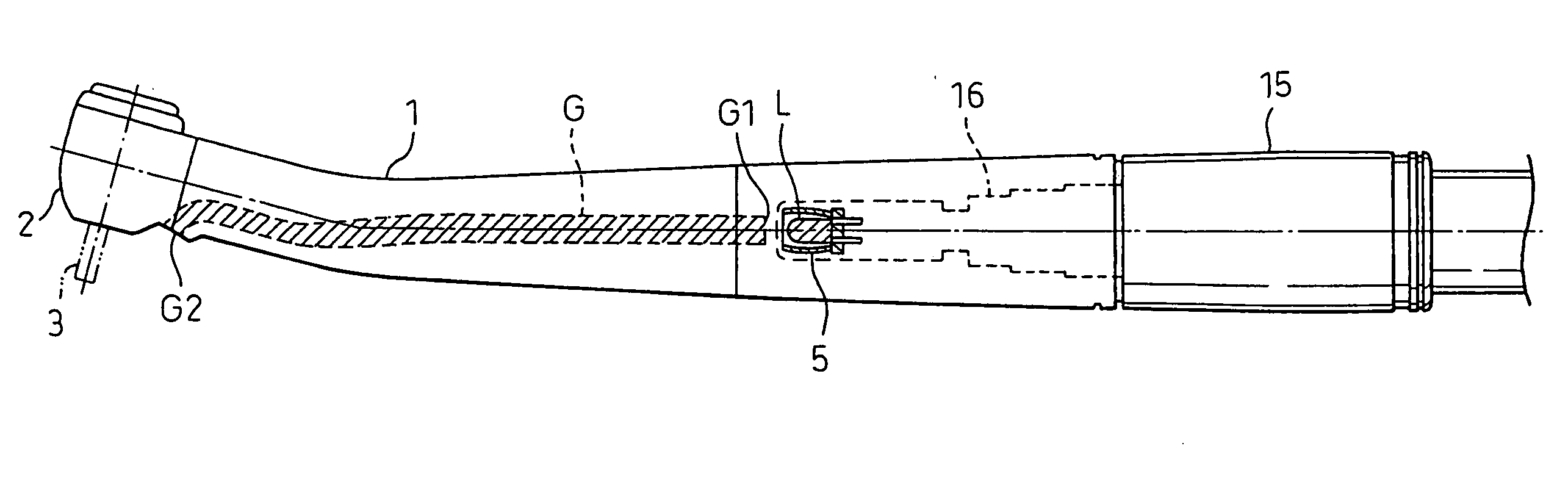
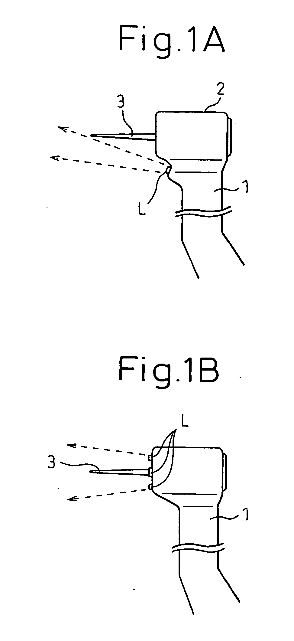
[0169] The first embodiment concerns the case where the light radiating means according to the present mode is applied to an air turbine handpiece; FIGS. 1A and 1B show the basic structure of the air turbine handpiece with the light radiating means mounted in its head.

[0170] In FIGS. 1A and 1B, reference numeral 1 is the handpiece body, 2 is the handpiece head, and 3 is a treatment tool such as a bar (one example of a diagnostic / treatment tool). In FIGS. 1A and 1B, a portion of the handpiece at the forward end thereof is shown, and for simplicity of explanation, the other portions are not shown here, but actually the handpiece is provided, at the end opposite from the head 2, with a joint which is detachable from the handpiece 1 and which is connected via a tube to a supply device such as an air supply device.

[0171] In FIG. 1A, the light radiating means comprises a light-emitting device L constructed from an LED or a semiconductor laser; here, the light-emitting device L is mounte...

embodiment 2

[0213] While the first embodiment has been described with reference to the first to ninth specific examples in connection with the case where the light radiating means according to the present mode is applied primarily to an air turbine handpiece (FIGS. 8 and 9 show examples in which it is applied to a scaler), the second embodiment described hereinafter relates to the case where the light radiating means according to the present mode is applied to a micromotor handpiece.

[0214] There are two types of micromotor handpiece: the contra-angle handpiece in which the axis of rotation of the treatment tool (diagnostic tool) 3 is substantially at right angles to the axis of the grip of the micromotor, and the straight handpiece in which the axis of rotation of the treatment tool (diagnostic tool) 3 coincides with the axis of the grip of the micromotor. The former type is shown as a 10th specific example in FIG. 13, and the latter type is shown as an 11th specific example in FIG. 14.

[0215]...

embodiment 3

[0227] Next, referring to FIGS. 17 to 21, the third embodiment will be described which concerns the case where the light radiating means according to the present mode is applied to a scaler handpiece. FIGS. 17A and 17B show the basic structure of the light radiating means according to the present mode as applied to the scaler handpiece; in particular, the portion centering around the forward end of the handpiece body 1 is shown in FIGS. 17A and 17B.

[0228] In FIG. 17A, the light-emitting device L is mounted exposed in one specific position near the portion of the forward end 18 to which the treatment tool (diagnostic tool) 3 is attached. The mounting position is slightly tilted, the tilt angle being chosen according to the shape of the treatment tool 3, i.e., the scaler, so that the optical axis of the light-emitting device, when mounted, is directed toward the tip of the scaler, as shown by dashed lines. Here, the light-emitting device L may be covered with an optically transmissiv...


PUM


Abstract

A diagnostic/treatment instrument such as a handpiece equipped with a dental treatment tool, etc. is provided with a light radiating unit that can distinctively detect a dental lesion, to facilitate the treatment of the lesion. A light source for emitting light that can distinctively detect the lesion is mounted near the head of the handpiece to which a diagnostic/treatment tool can be attached. The light emitted from the light source illuminates an area forward of the diagnostic/treatment tool. Alternatively, the light source comprises a plurality of light-emitting devices which are arranged around the periphery of the forward end of the handpiece head in such a manner as to encircle the diagnostic/treatment tool, and radiates light to illuminate the area forward of the diagnostic/treatment tool. When an oral cavity is illuminated with the light, a clinician can observe reflected fluorescent light by using a filtering function that passes the fluorescent light, and thus the clinician can perform the treatment while checking the lesion.

Description

TECHNICAL FIELD [0001] The present invention relates to a dental diagnostic and treatment apparatus, and more particularly to a dental diagnostic and treatment apparatus in which a dental diagnostic / treatment instrument such as a handpiece equipped with a treatment tool such as a tool used for the treatment of teeth is provided with a light radiating means having a light source capable of emitting light with which a dental lesion can be distinctively detected, thereby facilitating the treatment of the lesion. BACKGROUND ART [0002] In dental diagnosis and treatment, dentists make full use of various handpieces (or instruments), such as a dental air turbine handpiece, a dental micromotor handpiece, a dental scaler handpiece, a dental three-way syringe, a dental mirror, a vacuum syringe, a dental photo-polymerization device, a laser handpiece, and a dental tooth cleaning device, equipped with such tools as a dental drilling tool, a dental plaque / tartar removing tool, a treatment area r...

Claims


Application Information

Patent Timeline
IPC IPC(8): A61N5/10H05G2/00G21G4/00H01J35/00A61B1/24A61C1/08
CPCA61B1/24A61B5/0088A61C1/088A61B1/043A61B1/0615A61B1/0684A61B1/0605A61C19/004A61C1/08A61C19/04
Inventor OKAWA, SHINICHIKINO, KENJIMATOBA, KAZUNARI
Owner MORITA MFG CO LTD
Why Eureka
Try Eureka