
Method and apparatus for identifying physical features in video

a physical feature and video technology, applied in the field of methods and apparatus for identifying physical features in video, can solve the problems of less reliable estimation, less accurate, and less reliable passive ranging, and achieve the effect of increasing accuracy and reliability

Active Publication Date: 2007-05-31
HONEYWELL INT INC
View PDF5 Cites 21 Cited by
  • Summary
  • Abstract
  • Description
  • Claims
  • Application Information

AI Technical Summary

Benefits of technology

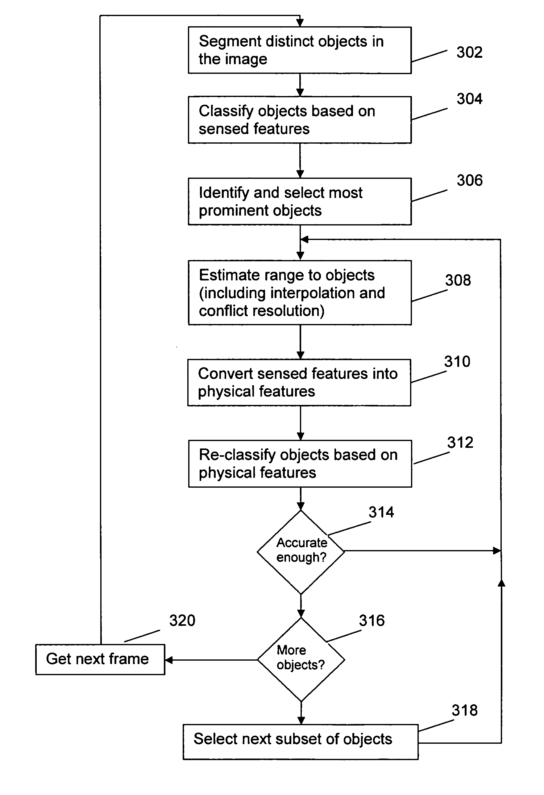
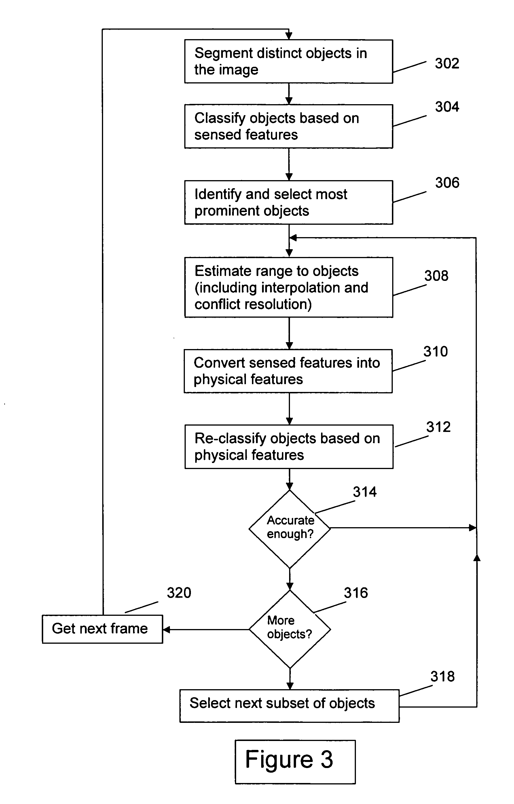
[0017] In an even further embodiment of the invention, when this process is completed, a next frame of video can be obtained and the process repeated for that frame. Range estimates from previous frame can be re-used in the case of a stationary camera scenario. Knowledge that an object in two or more frames is the same object can be used to even further increase accuracy and reliability. However, correlation of objects from frame to frame is not necessary.

Problems solved by technology

A similar problem exists with respect to estimating the speed of an object.
However, generally, such factors as oblique motion and lack of knowledge as to size make the estimate much less reliable.
Accordingly, passive ranging generally is much less reliable and less accurate than laser ranging and triangulation in stereo imaging.
Further, it can only be applied to moving objects (and then not particularly accurately if the speed, size, and / or direction of motion is not well known or predicted).
Laser ranging and triangulation in stereo imaging, while been relatively accurate and reliable, is expensive.
In addition, establishing stereo correspondence, for example, through dynamic programming, requires intense computations.
Furthermore, retrofitting pre-existing video surveillance systems for laser ranging or stereo imaging is extremely labor-intensive.

Method used


Image

  • Method and apparatus for identifying physical features in video
  • Method and apparatus for identifying physical features in video
  • Method and apparatus for identifying physical features in video

Examples


Embodiment Construction

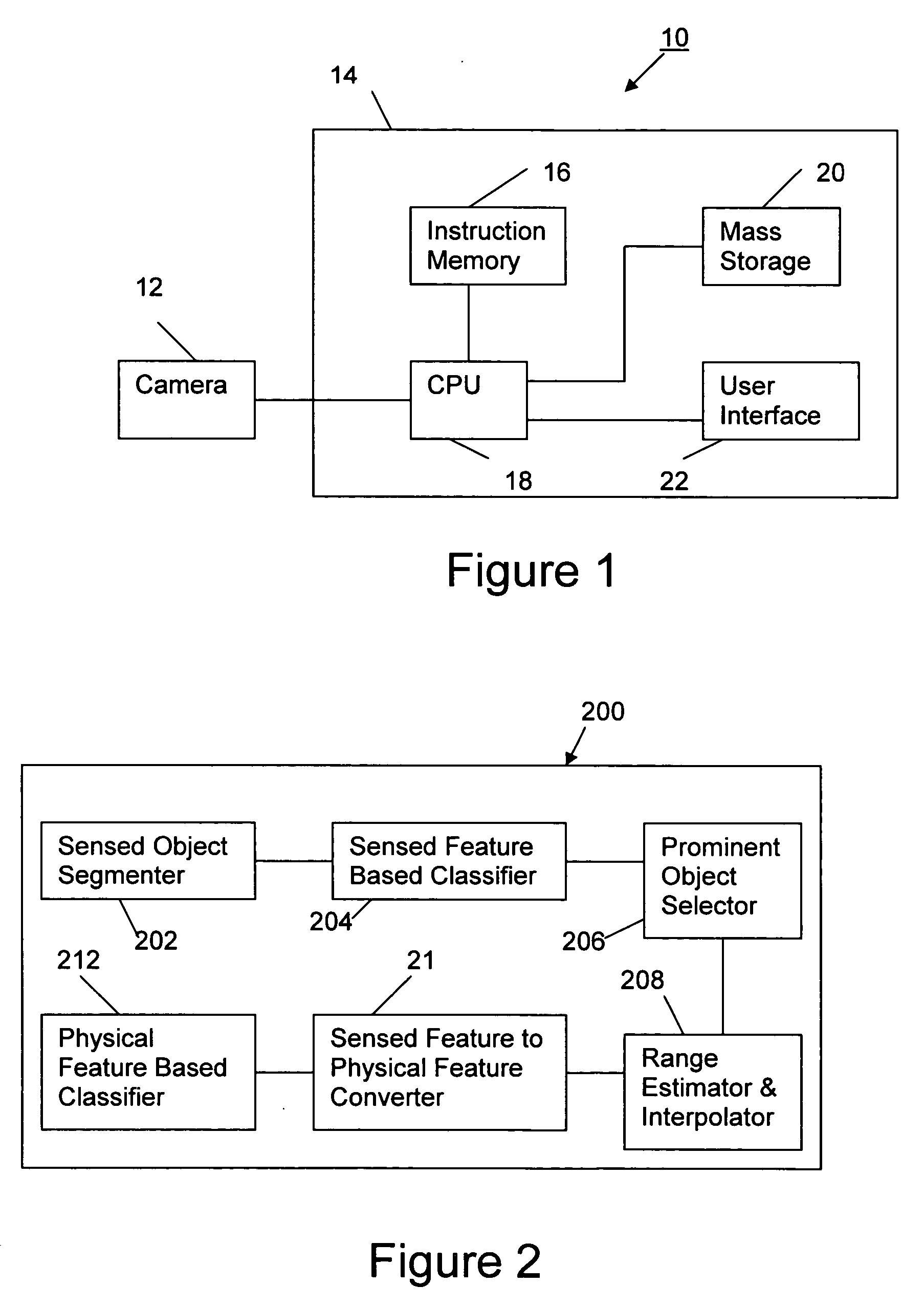
[0021] The present invention is a method and apparatus for processing image data in order to recognize and identify objects within an image, including multiple-frame video images. The key aspects of the present invention focus on the technique for classifying objects, either moving or stationary, and determining their range. The invention can be implemented through software loaded on a computing device, such as a microprocessor, processor, or PC. It can be embodied within a video surveillance system or separately connected to a video surveillance system. Alternately, the invention can be implemented by any other reasonable means including an application specific integrated circuit (ASIC), digital hardware, or any combination of the aforementioned.

[0022]FIG. 1 is a block diagram showing the major components of a video surveillance system 101 within which the present invention is incorporated. The system comprises one or more cameras 104 that output digital images of one or more surv...


PUM


Abstract

An image is processed by a sensed-feature-based classifier to generate a list of objects assigned to classes. The most prominent objects (those objects whose classification is most likely reliable) are selected for range estimation and interpolation. Based on the range estimation and interpolation, the sensed features are converted to physical features for each object. Next, that subset of objects is then run through a physical-feature-based classifier that re-classifies the objects. Next, the objects and their range estimates are re-run through the processes of range estimation and interpolation, sensed-feature-to-physical-feature conversion, and physical-feature-based classification iteratively to continuously increase the reliability of the classification as well as the range estimation. The iterations are halted when the reliability reaches a predetermined confidence threshold. In a preferred embodiment, a next subset of objects having the next highest prominence in the same image is selected and the entire iterative process is repeated. This set of iterations will include evaluation of both of the first and second subsets of objects. The process can be repeated until all objects have been classified.

Description

FIELD OF THE INVENTION [0001] The invention pertains to the estimation of ranges to pixels and the automated identification (calculation) of physical features in video images. BACKGROUND OF THE INVENTION [0002] Due to advances in video processing technology as well as the general increase in processing power available for a given cost and size, software is now available that is intended to examine live or recorded video and automatically recognize physical features in the video and determine the nature of objects appearing in the video, e.g., a car, an animal, a building, a human, etc. One well-publicized use of such technology is for automated recognition of individuals in video surveillance cameras by facial or other features. This technology, for instance, could be useful for automatically recognizing known terrorists or detecting abnormal or unusual activities and behaviors of people, vehicles and other objects of interest in airports and other public venues. [0003] Another appl...

Claims


Application Information

Patent Timeline
IPC IPC(8): G06K9/62G06K9/46G06V10/40
CPCG06K9/00771G06K9/46G06V20/52G06V10/40
Inventor AU, KWONG WINGBAZAKOS, MICHAEL E.MA, YUNQIAN
Owner HONEYWELL INT INC
Learn More