Method and system for measuring receiver mixer iq mismatch

a receiver mixer and iq mismatch technology, applied in the field of transceivers, can solve the problems of low-cost and highly integrated wireless systems, difficult or impossible to implement such filters as an integrated system, and the advantages of 802.11a come at a cos

a receiver mixer and iq mismatch technology, applied in the field of transceivers, can solve the problems of low-cost and highly integrated wireless systems, difficult or impossible to implement such filters as an integrated system, and the advantages of 802.11a come at a cos

US20070123188A1Inactive Publication Date: 2007-05-31AVAGO TECH INT SALES PTE LTD

Image

  • Method and system for measuring receiver mixer iq mismatch
  • Method and system for measuring receiver mixer iq mismatch
  • Method and system for measuring receiver mixer iq mismatch

Examples


Embodiment Construction

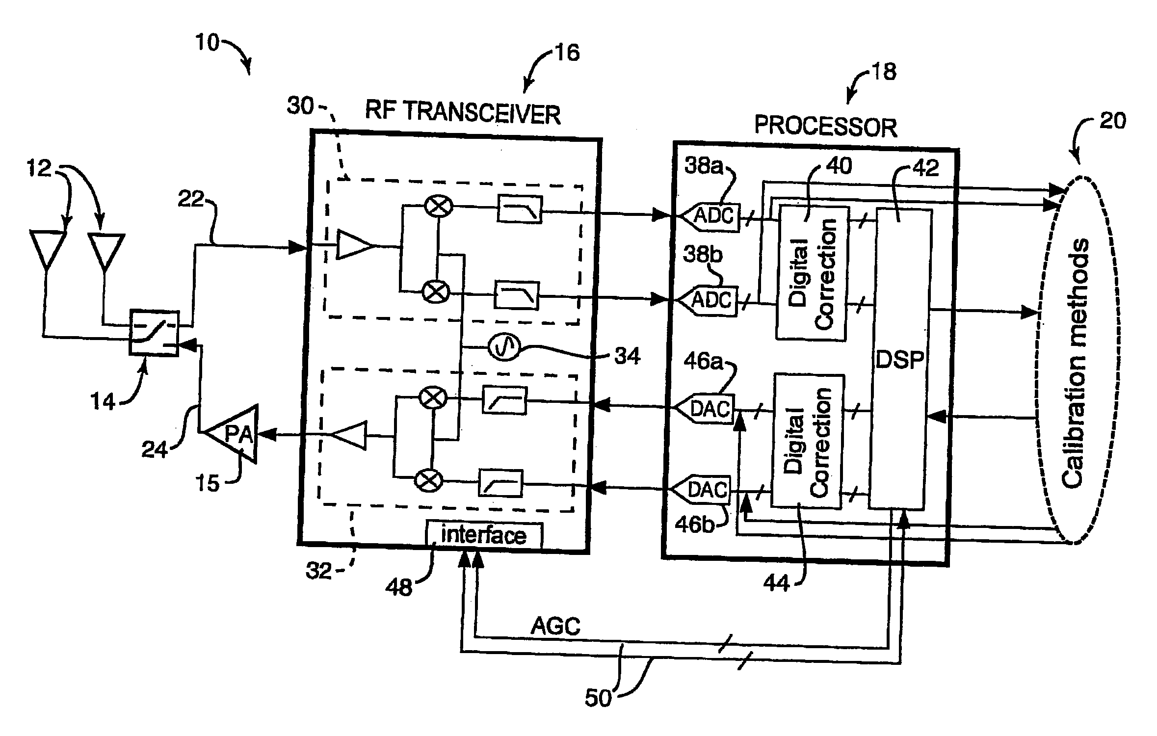
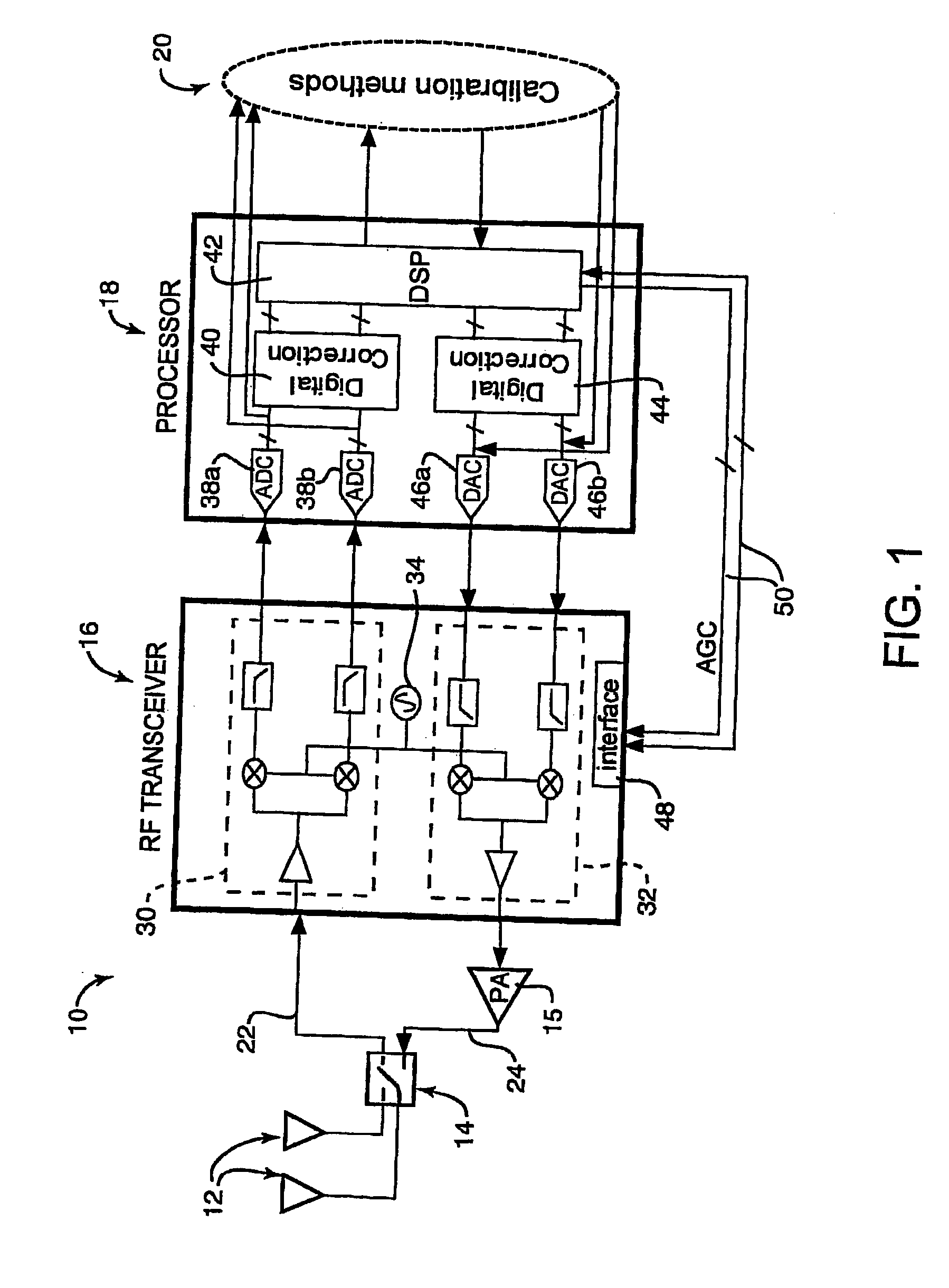
[0016] The present invention relates to estimating the receiver mixer IQ mismatch and digitally compensating the mismatch. The following description is presented to enable one of ordinary skill in the art to make and use the invention and is provided in the context of a patent application and its requirements. Various modifications to the preferred embodiment and the generic principles and features described herein will be readily apparent to those skilled in the art. Thus, the present invention is not intended to be limited to the embodiments shown but is to be accorded the widest scope consistent with the principles and features described herein.

[0017] Embodiments and examples of the present invention are described below. While particular applications and methods are explained, it should be understood that the present invention can be used in a wide variety of other applications and with other techniques within the scope of the present invention.

[0018]FIG. 1 is a block diagram o...


PUM


Abstract

Aspects for measuring receiver mixer IQ mismatch in a transceiver are described. The measuring includes providing a training signal for a receiver mixer, the training signal having periodic, uncorrelated I and Q signals. A phase mismatch in the receiver mixer is determined from IQ correlation over a unit period. A gain mismatch in the receiver mixer is determined from a power estimate of both I and Q signal for the unit period.

Description

CROSS REFERENCE TO RELATED APPLICATIONS [0001] The present application claims the benefit of U.S. Provisional Patent Application No. 60 / 445,525, filed Feb. 7, 2003, entitled, “Receiver IQ phase and gain mismatch digital calibration,” which is incorporated herein by reference in its entirety.FIELD OF THE INVENTION [0002] The present invention relates to transceivers, and more particularly to estimating the receiver mixer IQ mismatch and digitally compensating the mismatch. BACKGROUND OF THE INVENTION [0003] One increasingly popular application for wireless systems are wireless local area networks (WLANs) of computer systems. Prominent in the field of home and business, wireless computer networks include the wireless standards known as 802.11. The first standard to be available in commercial products was 802.11b. However, increasing demand for higher capacity in the growing wireless LAN market has led to the introduction of a new generation of WLAN standards using more spectrally effi...

Claims


Application Information

Patent Timeline
31 May 2007
Publication
US20070123188A1
IPC
H04B1/18; H04B1/10; H03D3/00; H04B1/30
CPC
H03D3/009; H04B1/30
Inventors
MO, LARRY Y. L.; YAMANAKA, AKIRA