Lng vapor handling configurations and methods

a technology of vapor handling and configuration, applied in the field of lng processing, can solve the problems of uneconomical, inpractical configuration, and high energy and operator attention required for vapor compression and vapor absorption systems, and achieve the effect of enhancing condensation

Inactive Publication Date: 2007-06-07
FLUOR TECH CORP
View PDF18 Cites 59 Cited by
  • Summary
  • Abstract
  • Description
  • Claims
  • Application Information

AI Technical Summary

Benefits of technology

[0013] Moreover, in yet further contemplated aspects, the fractionator may further be configured to provide liquefied petroleum gas (LPG) as a bottom product. In such configurations, the fractionator may be configured to receive another portion of the liquefied natural gas liquid as condensation refrigerant after the liquefied natural gas liquid provided refrigeration for condensation of the C2 and lighter components to enhance condensation.

Problems solved by technology

Therefore, vapor compression and vapor absorption systems generally require significant energy and operator attention, and particularly during transition from normal holding operation to ship unloading operation.
However, such configurations are often impractical and generally fail to eliminate the need for vapor recompression in LNG receiving terminals.
However, where a compressed gas is not readily available from another process, generation of the compressed gas is energy intensive and uneconomical.
While Prim's system increases the energy efficiency as compared to other systems, various disadvantages nevertheless remain.
For example, vapor handling in Prim's system is typically limited to plants in which production of a methane rich stream is desired.
While such a system typically provides improvements of control and mixing devices in a vapor condensation system, it nevertheless inherits most of the disadvantages of known configurations as shown in Prior Art FIG. 1.
While LNG with heavier contents or higher heating value can be produced at lower costs at the source, they are often not suitable for the North American market.
Unfortunately, most of the currently known processes and configurations for LNG ship unloading and regasification fail to address various difficulties.
Among other things, many of the known processes require vapor compression and absorption that are energy inefficient.
Still further all or almost all of the known processes fail to economically remove heavy hydrocarbons from LNG to meet stringent environmental standards.

Method used


Image

  • Lng vapor handling configurations and methods
  • Lng vapor handling configurations and methods
  • Lng vapor handling configurations and methods

Examples


Embodiment Construction

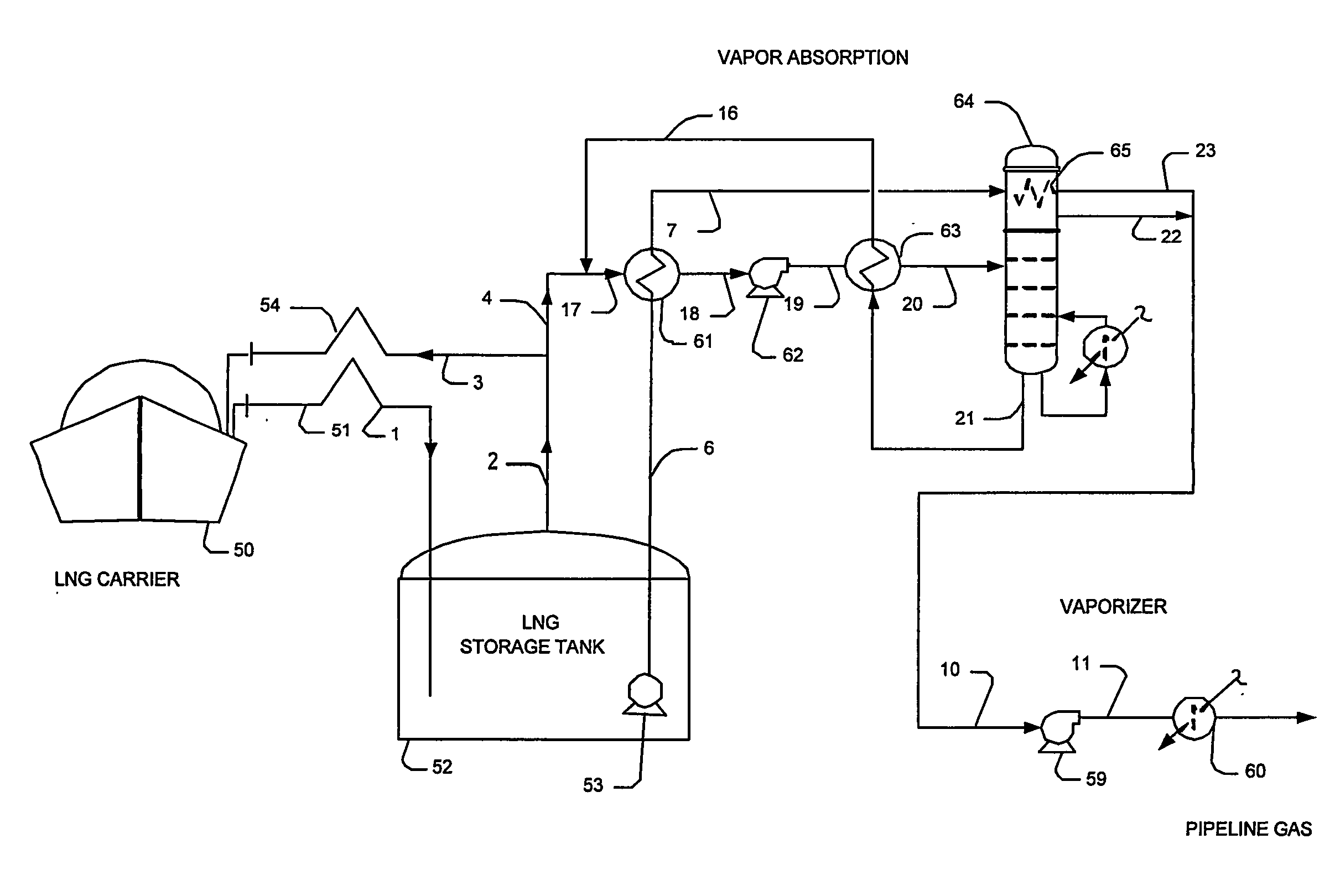
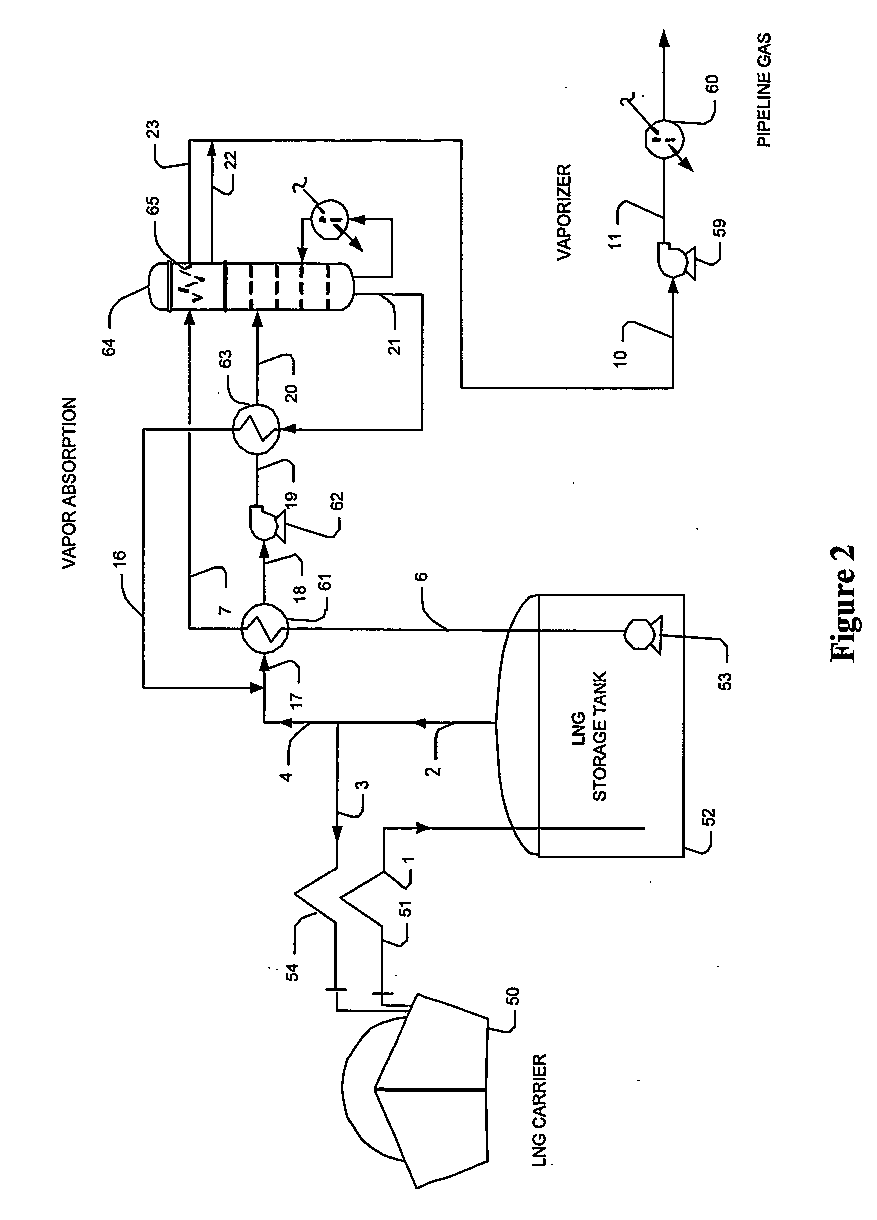
[0020] The present invention is generally directed to configurations and methods of LNG vapor handling in which the vapor (in most cases predominantly comprising N2, C1 and C2) is combined with a heavier hydrocarbon (in most cases predominantly comprising C3, C4 and heavier components) to form a hydrocarbon mixture having a condensation temperature that is higher than that of the LNG vapor. The so generated mixture is subsequently condensed using the refrigeration content of the LNG liquid and the liquid is pumped to a higher pressure. The pressurized mixture is then heated, and (C2 and lighter) vapor is separated from the mixture in a fractionator at elevated pressure. The fractionator overhead vapor is condensed using the refrigeration content of the LNG liquid, while the heavier hydrocarbon produced by the fractionator is recycled to the point of combination with LNG vapor.

[0021] In a particularly preferred aspect of the inventive subject matter, contemplated configurations and ...


PUM


Abstract

LNG vapor from an LNG storage vessel is absorbed using C3 and heavier components provided by a fractionator that receives a mixture of LNG vapors and the C3 and heavier components as fractionator feed. In such configurations, refrigeration content of the LNG liquid from the LNG storage vessel is advantageously used to condense the LNG vapor after separation. Where desired, a portion of the LNG liquid may also be used as fractionator feed to produce LPG as a bottom product.

Description

[0001] This application claims the benefit of U.S. provisional patent applications with the Ser. Nos. 60 / 517,298 (filed Nov. 3, 2003) and 60 / 525,416, (filed Nov. 25, 2003), both of which are incorporated by reference herein.FIELD OF THE INVENTION [0002] The field of the invention is LNG processing, especially as it relates to LNG vapor handling during LNG ship unloading or transfer. BACKGROUND OF THE INVENTION [0003] LNG ship unloading is in many cases a critical operation that requires efficient integration with a regasification operation. Typically, when LNG is unloaded from an LNG ship to a storage tank, LNG vapors are generated from the storage tank due to volumetric displacement, heat gain during LNG transfer and in the pumping system, storage tank boiloff, and flashing due to the pressure differential between the ship and the storage tank. In most cases, the vapors need to be recovered to avoid flaring and pressure buildup in the storage tank system. [0004] In a typical LNG re...

Claims


Application Information

Patent Timeline
Patent Type & Authority Applications(United States)
IPC IPC(8): F25J3/00F17C9/02F17C3/00F17C6/00F17C9/00F25J1/02F25J3/02
CPCF17C3/00F17C5/06F17C6/00F17C9/00F17C9/04F17C2201/052F17C2205/0364F17C2205/0367F17C2221/033F17C2221/035F17C2223/0161F17C2223/033F17C2223/043F17C2223/047F17C2225/0123F17C2225/0153F17C2225/0161F17C2225/033F17C2225/035F17C2225/036F17C2225/047F17C2227/0128F17C2227/0135F17C2227/0157F17C2227/0178F17C2227/0185F17C2227/0306F17C2227/0309F17C2227/0318F17C2227/0327F17C2227/0339F17C2227/0388F17C2227/0393F17C2250/0636F17C2250/0642F17C2260/02F17C2260/031F17C2260/056F17C2265/015F17C2265/022F17C2265/025F17C2265/03F17C2265/033F17C2265/034F17C2265/036F17C2265/037F17C2265/05F17C2270/0105F17C2270/0123F17C2270/0136F25J3/0214F25J3/0233F25J3/0242F25J2200/02F25J2205/90F25J2210/04F25J2210/62F25J2210/90F25J2235/60F25J2245/02F25J2245/90F25J2270/904F25J2290/62F25J3/0209F25J2200/72
Inventor MAK, JOHNNIELSEN, RICHARD B.GRAHAM, CURT
Owner FLUOR TECH CORP
Why Eureka
Try Eureka