[0011] The present invention has been accomplished in view of the above-mentioned problems of the prior art, and an object of the present invention is to provide a control apparatus for a gas sensor which can suppress not only splash water cracking of a detection element, but also condensation water cracking thereof at the time of
cold start of an
internal combustion engine.
[0014] As described above, in the present invention, when it is determined that condensation water within the exhaust
pipe is being generated, using the pre-
electrification means, electrical power is supplied to the heater so as to render the temperature of the detection element equal to or higher than 100° C. Therefore, even in the case where condensation water adheres to the surface of the detection element from the beginning of
cold start of the internal
combustion engine, or when condensation water adheres to the surface of the detection element immediately after the cold start,
evaporation of such condensation water is accelerated during pre-
electrification. Further, the pre-electrification means supplies electrical power to the heater for maintaining the temperature of the detection element within a range below the splash-water-cracking generation temperature, while rendering the temperature of the detection element equal to or higher than 100° C. Therefore, even when condensation water adhering to the detection element evaporates during pre-electrification, the
temperature difference between the detection element and the heater can be suppressed to a small level, whereby generation of condensation water cracking during pre-electrification can be prevented.
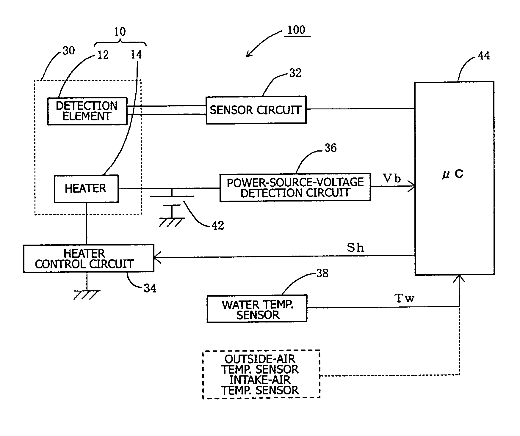
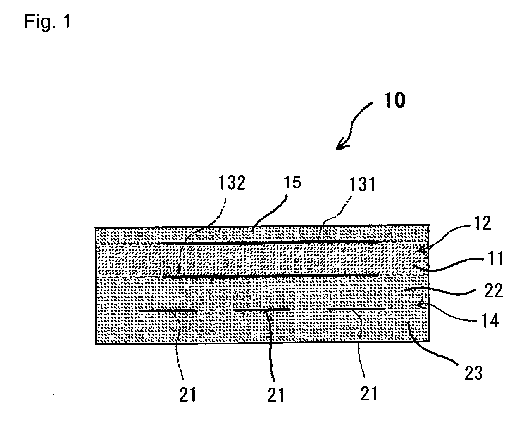
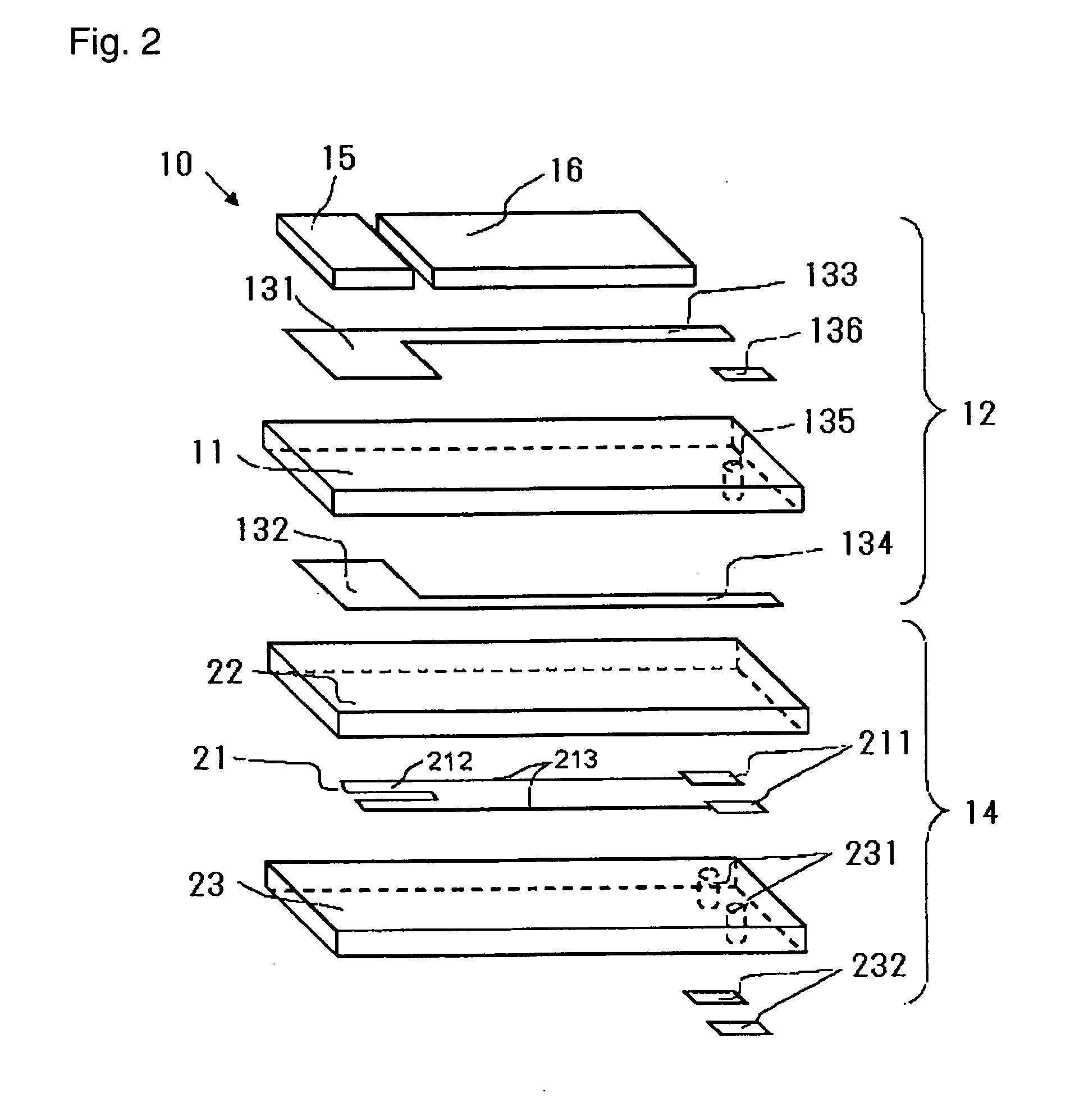
[0016] Notably, in the present invention, no particular limitation is imposed on the manner of providing the heater insofar as the heater is disposed near the detection element. For example, when the detection element is formed in the shape of a bottomed cylinder, the heater may be inserted into the interior of the detection element. When the detection element is formed in the shape of a plate extending along the longitudinal direction, the heater may be laminated on the detection element. Notably, in the case where the heater is laminated on the plate-shaped detection element, the detection element and the heater may be fired as a unitary member, or the detection element and the heater may be bonded together via a bonding layer. In particular, a gas sensor element having a structure in which a plate-shaped detection element and a plate-shaped heater are laminated can be made compact as compared with the case of a cylindrical gas sensor element (detection element), and during pre-electrification, can considerably accelerate the
evaporation of condensation water adhering to the detection element. Therefore, a gas sensor element used for the gas sensor control apparatus of the present invention preferably has a structure in which a plate-shaped detection element and heater are layered. A well-known
power control method may be used for supplying electrical power (predetermined electrical power) to the heater using pre-electrification means or heater electrification means. An example of the known
power control method includes PWM (
pulse width modulation) control.
[0017] In the above-described control apparatus for a gas sensor, the condensation water determination means preferably determines whether condensation water within the exhaust pipe is generated, on the basis of temperature of cooling water of the internal
combustion engine. Because the
cooling water temperature is strongly correlated with the wall temperature of the exhaust pipe, such determination can be performed accurately in a simple manner.
[0019] Condensation water cracking may occur not only when condensation water adheres to the detection element before startup of the internal
combustion engine, but also when a droplet of condensation water flying within the exhaust pipe adheres to the detection element after start of supply of
electricity to the heater but before the temperature of the detection element reaches 100° C. In view of the above, in the present invention, during a predetermined period of time after condensation water is determined to be generated, electrical power at a relatively high first
power level is supplied to the heater so as to cause the temperature of the detection element to quickly reach 100° C. After that, electrical power at a second
power level lower than the first
power level is supplied to the heater. With this operation, condensation water cracking of the detection element at the time of cold start of the internal combustion engine can be prevented more reliably.
[0020] Moreover, in the above-described control apparatus for a gas sensor, the pre-electrification means preferably calculates, on the basis of a
voltage value of the power source
voltage, a duty ratio of the
voltage waveform applied to the heater, and controls supply of electricity to the heater by
pulse width modulation (PWM) to thereby supply electrical power to the heater at the first and second power levels. PWM control is advantageous in that the power supplied to the heater can be easily adjusted by controlling its duty ratio. Therefore, during pre-electrification, through PWM control of supply of electrical power at the first and second power levels, supply of electricity to the heater can be accurately controlled without use of a complex control method.

