[0009]The
system and process of the present invention potentially resolve many of the drawbacks of existing modified Claus sulfur recovery plants by offering smaller, less complicated, more efficient equipment that is less costly to build than conventional sulfur recovery plants, and make possible the expansion of sulfur recovery process capacity. Advantageously, the new system and process are intended to provide for better control or regulation of catalyst and reactant gas temperatures so that more efficient and selective performance of the Claus catalysts is made possible. Some of the drawbacks of conventional sulfur recovery processes are also avoided by employing a new sulfur recovery process that has the operational
advantage of using a partial oxidation short
contact time reactor instead of a free
flame combustion chamber. In the partial oxidation short
contact time reactor
oxygen is reacted with H2S in the feed gases primarily via direct partial oxidation of the H2S, according to the chemical reactionH2S+½O2→1 / xSx+H2O (4)(x=2, 6 or 8, depending on the
temperature and pressure).
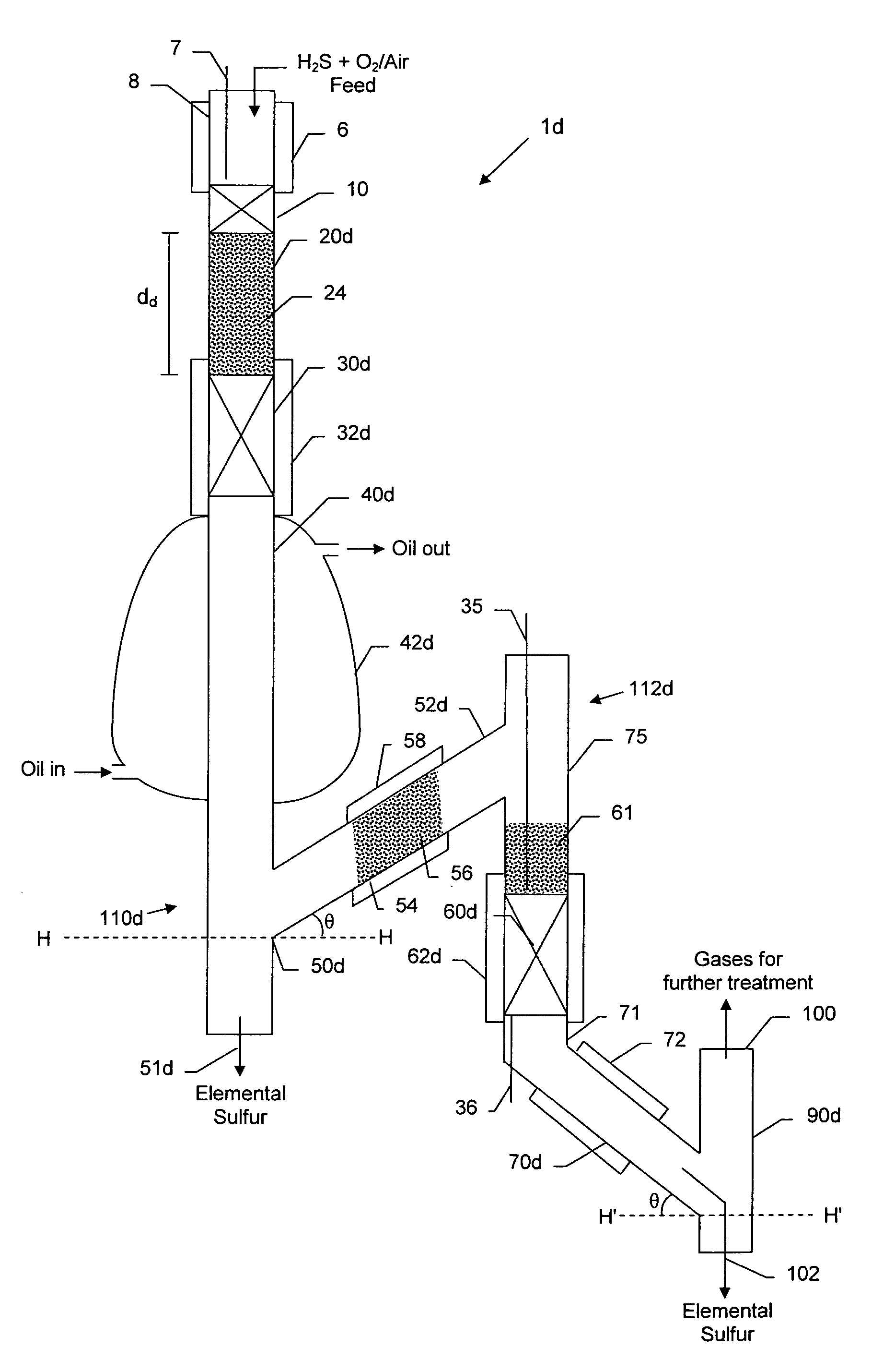
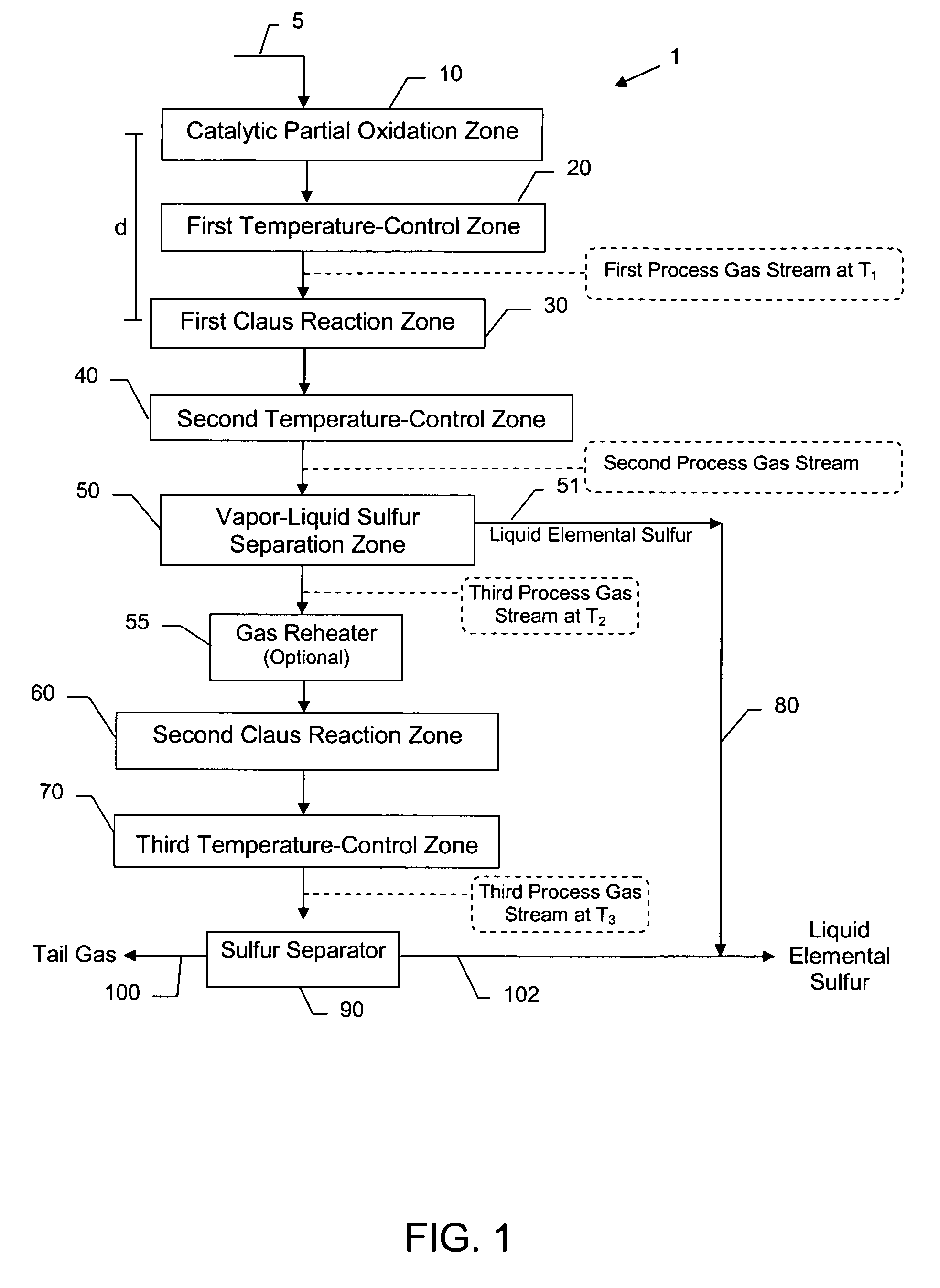
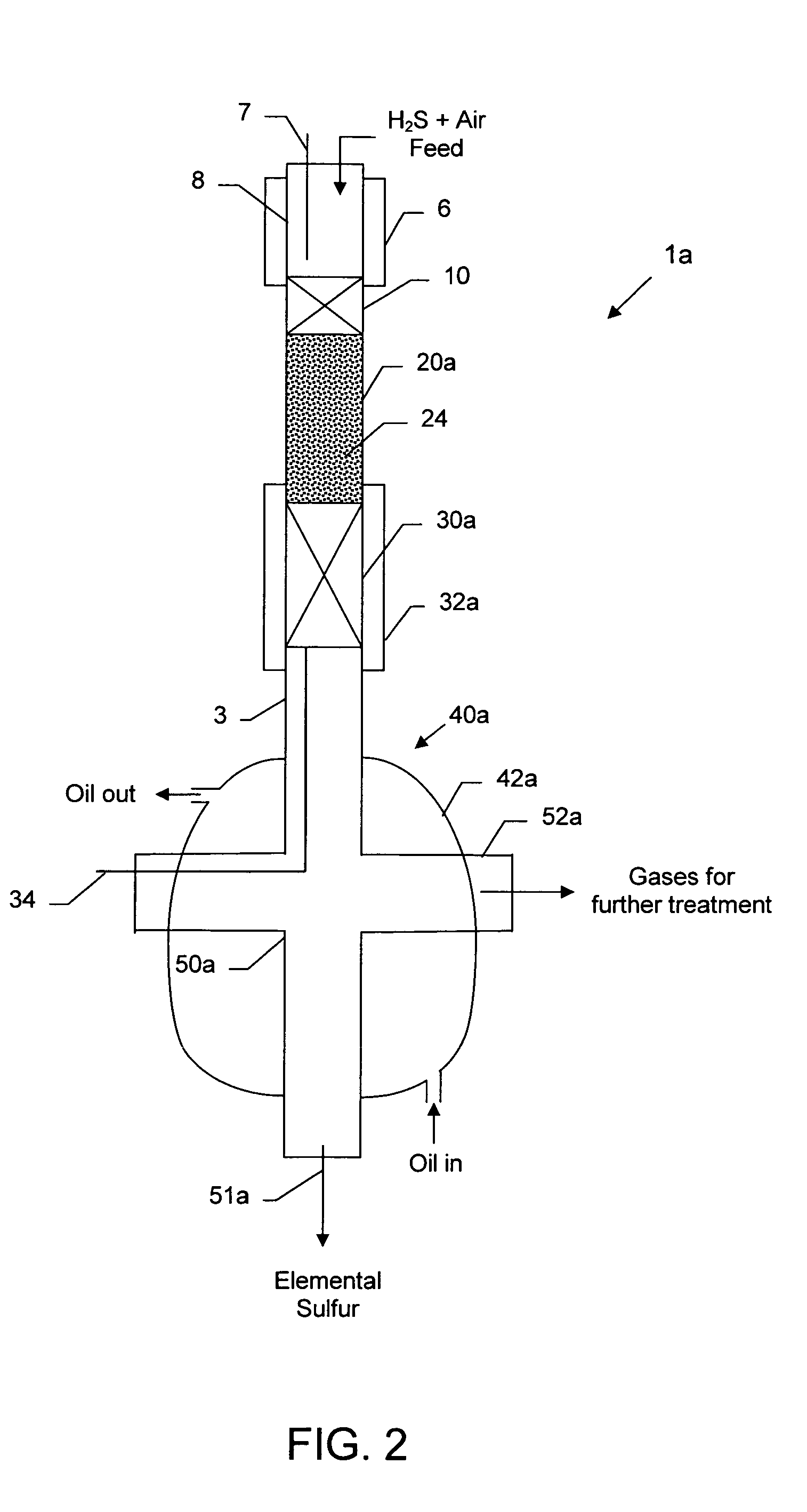
[0011]In accordance with certain embodiments of the present invention a compact sulfur recovery system is provided comprising a plurality of components in serial fluid flow arrangement. This arrangement includes a catalytic partial oxidation reaction zone capable of withstanding temperatures up to about 2,700° F. (1,482° C.), a first temperature-control zone, a first Claus catalytic reaction zone comprising a catalyst temperature-regulation device, a second temperature-control zone, a first vapor-liquid sulfur separation zone, a first liquid sulfur outlet, and a first effluent gas outlet. In some embodiments a
mixing zone precedes the catalytic partial oxidation reaction zone, and in some embodiments the system includes one or more temperature measuring devices. In some embodiments, the first temperature-control zone contains a
heat transfer enhancement medium. The system is preferably configured so as to deter the accumulation of liquid sulfur in the first Claus catalytic reaction zone, when the system is in operation in a downward flow process for recovering elemental sulfur from a H2S-containing gas
stream. For instance, in some embodiments the catalytic partial oxidation reaction zone, first temperature-control zone, first Claus catalytic reaction zone, second temperature-control zone, first vapor-liquid sulfur separation zone, and first liquid sulfur outlet are in a vertically oriented stacked arrangement. The vertically stacked arrangement discourages, deters or prevents accumulation of liquid sulfur on the catalyst, allowing condensed sulfur to drain down and away from the Claus catalyst when the system is in use.
[0013]In certain embodiments, the vapor-liquid separation zone is configured for operating in co-current downward flow mode, to deter re-entrainment of liquid sulfur in a gas
stream exiting the separation zone. In certain embodiments, the vapor-liquid separation zone is configured for promoting liquid drainage along a separate path than that of gas flowing to the gas outlet, and in certain embodiments, the vapor-liquid separation zone is configured to deter liquid sulfur accumulation in the separation zone.
[0018]In certain embodiments, a system according to the present invention comprises: (a) means for carrying out the partial oxidation of H2S to produce a first process gas
stream comprising primarily gaseous elemental sulfur, unconverted H2S and SO2; (b) means for adjusting the temperature of the first process gas stream to a temperature or temperature range that favors the conversion of H2S and SO2 according to the Claus reaction; (c) means for carrying out the Claus reaction of H2S and SO2 in the first process gas stream to produce a second process gas stream, the means comprising a first Claus catalyst at a temperature or temperature range favoring the Claus reaction; (d) means for deterring accumulation of liquid elemental sulfur on the first Claus-catalyst
bed; (e) means for adjusting the temperature of the second process gas stream to a temperature or temperature range that favors the condensation of elemental sulfur from the second process gas stream but deters or prevents condensation in a second Claus catalyst
bed; (f) means for separating elemental sulfur from the second process gas stream to make a third process gas stream; (g) means for carrying out the Claus reaction of H2S and SO2 in the third process gas stream to produce a fourth process gas stream, the means comprising the second Claus catalyst
bed; (h) means for deterring accumulation of condensed elemental sulfur on the second Claus catalyst bed; and (i) means for separating liquid elemental sulfur from the fourth process gas stream.
[0020]Also provided in accordance with certain embodiments of the present invention is a process for recovering elemental sulfur from a H2S-containing gas stream, the process including: (a) obtaining an above-described compact sulfur recovery system wherein at least one component of the system is configured to deter accumulation of liquid sulfur in the first Claus catalytic reaction zone; (b) introducing a feed gas stream comprising H2S and O2 into the catalytic partial oxidation reaction zone such that a first process gas stream comprising elemental sulfur, unreacted H2S, SO2 and water is produced; (c) in the first temperature-control zone, adjusting the temperature of the first process gas stream to a first predetermined temperature or temperature range that is no more than 650° F. (343° C.) and above the dewpoint of elemental sulfur prior to entry of the first process gas stream into the first Claus catalytic reaction zone; (d) deterring accumulation of liquid elemental sulfur on the first Claus catalyst; (e) adjusting the temperature of the second process gas stream to a temperature or temperature range between 300 and 450° F. (149–232° C.) that favors the condensation of elemental sulfur; (f) carrying out the separation of elemental sulfur from the vapor mixture in a vapor-liquid separation zone to produce a third process gas stream; (g) adjusting the temperature of the third process gas stream to a temperature or temperature range between 400 and 600° F. (204–315° C.) that favors the conversion of H2S and SO2 according to the Claus reaction; (h) carrying out the Claus reaction of SO2 and residual H2S in the third process gas stream over a second Claus catalyst to produce a fourth process gas stream comprising gaseous elemental sulfur and residual gas, wherein the Claus reaction is carried out at a catalyst temperature or temperature range between 400 and 600° F. (204–315° C.) that favors the conversion of H2S and SO2 according to the Claus reaction; (i) deterring accumulation of liquid elemental sulfur on the second Claus catalyst; (j) adjusting the temperature of the fourth process gas to a temperature or temperature range between 250 and 350° F. (121–177° C.) that favors condensation of elemental sulfur from the fourth process gas stream; (k) recovering condensed elemental sulfur; and (l) optionally, subjecting the residual gas to
tail gas treatment.
[0022]In certain embodiments of the process, the predetermined temperatures or temperature ranges (T1 and T2) (FIG. 1) also favor the condensation of gaseous elemental sulfur. In certain embodiments the temperature (T1) of the first process gas stream is maintained at a level above the
dew point of elemental sulfur, typically between 450° F. and 600° F. (about 232–315° C.), to prevent the condensation of liquid sulfur on the Claus catalyst surface. In certain embodiments the temperature of the third process gas stream (T2) is maintained in the range of 385° F. to 480° F. (about 196–249° C.) to prevent the condensation of liquid sulfur on the catalyst surface as the Claus reaction forms elemental sulfur. In certain embodiments, the temperature of the fourth process gas stream (T3) (FIG. 1) is maintained between 255° F. and 310° F. (about 124–154° C.) to produce a liquid
sulfur product with a low sulfur
vapor pressure, prevent the solidification of any elemental sulfur, and keep the
viscosity low. In some embodiments the above-described process includes maintaining a gas hourly
space velocity of the feed gas stream in the catalytic partial oxidation reaction zone of at least 20,000 h−1. In some embodiments the process includes maintaining a gas hourly
space velocity of the first process gas stream in the first Claus reaction zone of at least 10,000 h−1. In some embodiments the process includes maintaining a gas hourly
space velocity of the second process gas stream in the second Claus reaction zone of at least 5,000 h−1.

