Low NO.sub.x burner

a burner and burner technology, applied in the direction of gaseous fuel burners, combustion types, lighting and heating apparatus, etc., can solve the problems of increasing the overall volume of gas that must be transported, increasing initial installation costs as well as subsequent operation and maintenance costs, and reducing the flow velocity of gases. , the effect of stabilizing the flame at the spinner

Active Publication Date: 2014-08-05
JOHN ZINK CO LLC
View PDF26 Cites 2 Cited by
  • Summary
  • Abstract
  • Description
  • Claims
  • Application Information

AI Technical Summary

Benefits of technology

[0007]The present invention further improves on the low NOx burner described in the above-referenced copending patent application in that it eliminates the need for a tube enclosing the burner and simplifies the construction and operation of the burner as described below.
[0019]In operation following the initial lighting of the burner, the flame generated by the burner is anchored on the downstream end of the spinner, relatively remote from the front furnace wall on which the burner is mounted. Since the burner is not enclosed inside a tube or tubular member and the main air discharge ports are located relatively close to the furnace front wall, while the spinner is relatively remote from the wall and far inside the combustion chamber, the flow velocities of the fuel gas, combustion air and their mixture have decreased significantly by the time they reach the spinner. This avoids the problem encountered with typical prior art burners which are located inside and proximate the ends of surrounding tubular conduits where higher fuel gas-combustion air mixture velocities can lead to flame instabilities and relatively early flameouts when trying to achieve lowest NOx emissions. With the burner of the present invention, the discharged air and gases are not constrained to limited cross-sections and, therefore, they decelerate relatively quickly, which aids in stabilizing the flame at the spinner. Thus, the present invention lowers the flow velocity of gases surrounding the spinner, increases flame stability and significantly lowers the likelihood of flameouts, while lower NOx emissions are achieved with a burner that is less costly to build, install, maintain and operate than comparable prior art burners.
[0020]In addition, by placing all fuel gas spuds inside the radially outermost extent of the air ports and eliminating a burner throat traditionally formed by the furnace wall, the radial footprint of the burner (relative to the furnace wall) is reduced so that it occupies less space on the burner front wall and inside the furnace chamber. This feature is particularly advantageous for retrofitting existing furnaces with low NOx burners where size of the opening available for the burner is limited by the front wall water tubes (because presently available low NOx burners are typically significantly larger than conventional burners due to their need for higher FGR rates and additional features needed to lower the NOx).

Problems solved by technology

Flue gas typically has a temperature in the range of between about 200° F. to 400° F. Recirculated flue gas lowers flame temperatures and NOx generation, but in excessive amounts causes flame instability and blowout.
However, large amounts of FGR that might be necessary for reducing NOx substantially increase the overall volume of gas that must be transported through the burner and the furnace convection section.
This increases initial installation costs as well as subsequent operation and maintenance costs due to the increased energy requirements of the blower, all of which is undesirable.
However, this burner is susceptible to overheating and damage to the tube if fuel starts burning inside the confines of the tube.
Conditions for the fuel burning inside the tube may happen when the overall incoming mixture of air, flue gas and fuel gas is insufficiently diluted with inert gases like FGR.
Steering the operating regimes of the burner away from the flame burning inside also requires shifting more toward the discharge end of the tube that is usually not optimal for achieving the lowest NOx emissions.

Method used


Image

  • Low NO.sub.x burner
  • Low NO.sub.x burner
  • Low NO.sub.x burner

Examples


Embodiment Construction

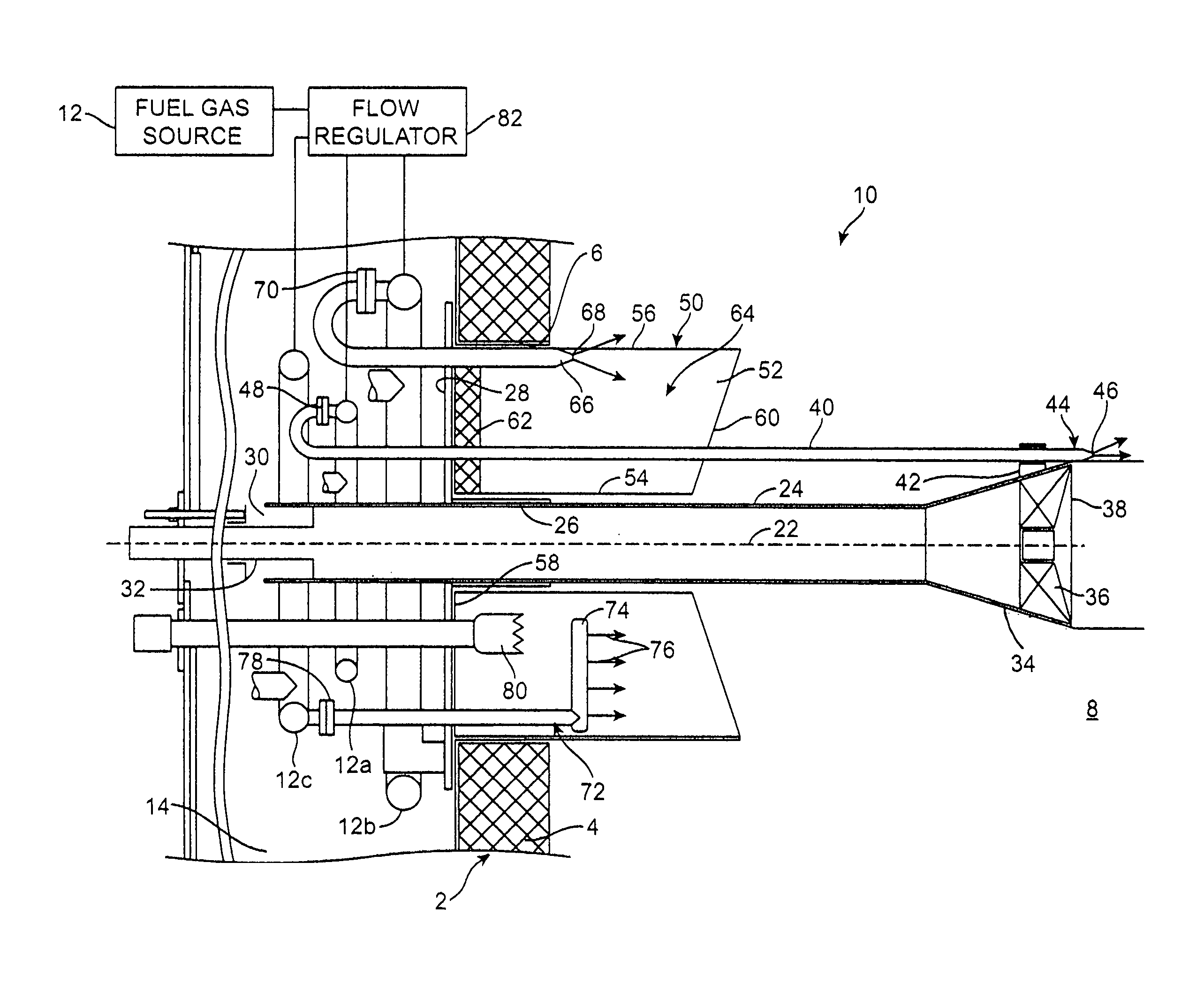
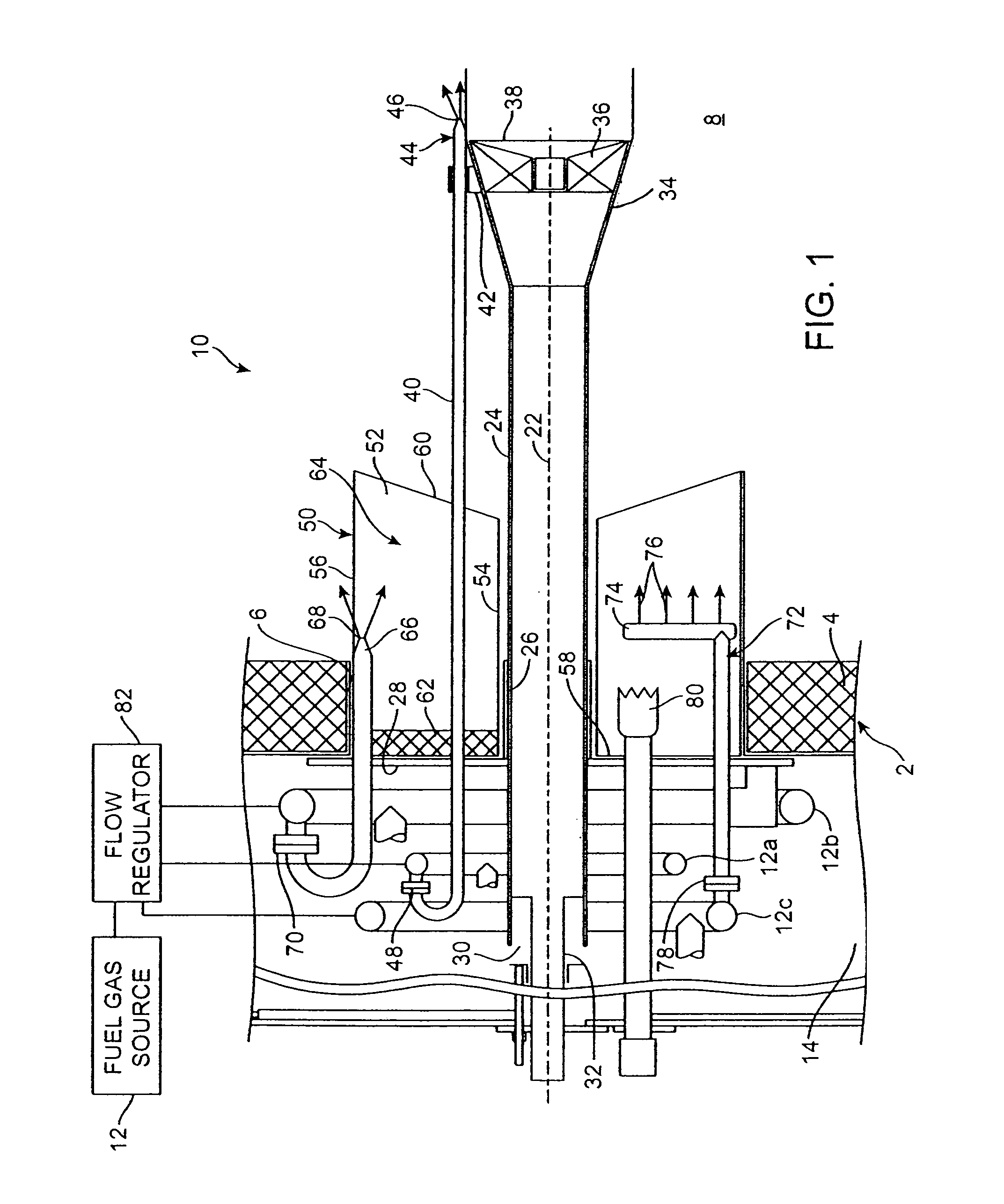
[0024]Referring to the drawings, a furnace 2 has a front wall 4 with an opening 6 that provides access into a combustion chamber 8 inside the furnace. A low NOx burner 10 constructed in accordance with the present invention extends through opening 6 into the combustion chamber of furnace 2, where it forms a flame 84 for generating heat. For example, the furnace may be a boiler that generates steam.

[0025]A fuel gas supply 12 and a combustion air supply 90 are suitably coupled to windbox 14 attached to furnace front wall 4. The burner directs the fuel and the combustion air into the combustion chamber, where they are mixed, ignited and combusted, thereby releasing heat energy and generating high temperature furnace gases which are typically discharged into a convection section 16 of the furnace where temperature is reduced, typically to a range between about 200-400° F. The cooled flue gas is discharged to the atmosphere through a stack 20. As will be explained in more detail later, a...


PUM


Abstract

A low NOx burner for installation on a furnace wall has an elongated tube connected to a combustion air supply, the furnace side end of which mounts a combustion air spinner that is spaced from the furnace wall. A plurality of air ports extend through the wall into the combustion chamber. Downstream ends of the air ports are spaced from the furnace wall as well as from the spinner, and they are configured to bias the discharged air flow towards the spinner. A plurality of first fuel gas spuds with fuel gas discharge orifices arranged about the spinner and discharges fuel gas into the combustion chamber downstream of the spinner. A second fuel gas spud is disposed in pockets between adjacent pairs of air ports which are closed against the furnace wall so that no combustion air flows through the pockets. The third gas spuds are placed inside the air ports.

Description

CROSS-REFERENCES TO RELATED APPLICATIONS[0001]This application is a continuation in part of U.S. patent application Ser. No. 11 / 067,312 filed Feb. 25, 2005 for an “Energy Efficient Low NOx Burner and Method of Operating Same”, the disclosure of which is incorporated herein by reference.BACKGROUND OF THE INVENTION[0002]The present invention relates to low NOx emitting burners which are compact, efficient to operate, and employ furnace gas recirculation inside the combustion chamber of the furnace to reduce NOx emissions.[0003]Furnace emissions are of great concern because they significantly contribute to atmospheric pollution. A large source for NOx emissions is burners as used in large and small furnaces, including, for example, very large furnaces used for generating electric power with steam-operated turbines. It is well known that NOx emissions are reduced by lowering the temperature of the flame generated by the burner inside the furnace. Conventionally this has been attained by...

Claims


Application Information

Patent Timeline
Patent Type & Authority Patents(United States)
IPC IPC(8): F23Q9/00
CPCF23C6/047F23C9/006F23C2900/09002F23D14/64F23D2900/00008F23D2900/14004
Inventor LIFSHITS, VLADIMIRLONDERVILLE, STEPHEN B.
Owner JOHN ZINK CO LLC
Why Eureka
Try Eureka