
Radiation system

a radiation system and accelerator technology, applied in the field of particle accelerators, can solve the problems of increasing the cost of the rf electron accelerator, low electron beam power usage efficiency, and insufficient data to discriminate materials of objects, so as to reduce the cost of building, operating and maintaining, and increase the efficiency of the radiation system. , the effect of increasing the efficiency of the radiation system

Active Publication Date: 2011-05-31
SCANTECHIBS IP HLDG
View PDF5 Cites 1 Cited by
  • Summary
  • Abstract
  • Description
  • Claims
  • Application Information

AI Technical Summary

Benefits of technology

"The present invention provides an apparatus and method for using multiple RF electron accelerators with a single RF generator. This allows for better irradiation of subject objects from different directions and in multiple planes, increasing the efficiency of the radiation system and allowing for the treatment of thicker objects. The radiation systems can also be used in inspection systems to generate images of the contents of containers or volumes from different directions and in multiple views or planes. The use of a single RF generator reduces the cost of the system and allows for the generation of multiple views of the contents of a container or volume while substantially reducing the cost of doing so."

Problems solved by technology

Unfortunately, such ferrite uncouplers cause the loss of some of the power produced by the RF generators and, hence, increase the cost of the RF electron accelerators as RF generators capable of producing more power must be utilized to account for the subsequent power losses.
In such configurations, the depth of sterilization, pasteurization, disinfestation, or decontamination into an object is, typically, small and the usage efficiency of electron beam power is low.
Further, in such inspection systems, the generated data is insufficient to discriminate materials of the objects.
However, the use of two or more RF electron accelerators would require two or more RF generators, two or more power supplies for the RF generators, and two or more control systems, thereby significantly complicating the alternative systems and increasing their cost.

Method used


Image

  • Radiation system
  • Radiation system
  • Radiation system

Examples


Embodiment Construction

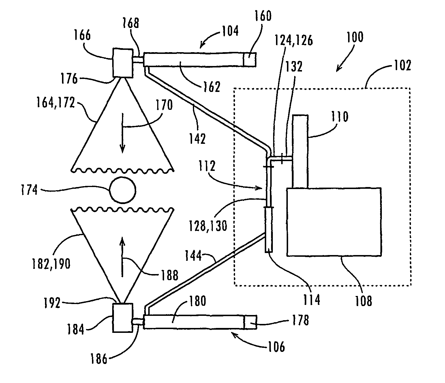
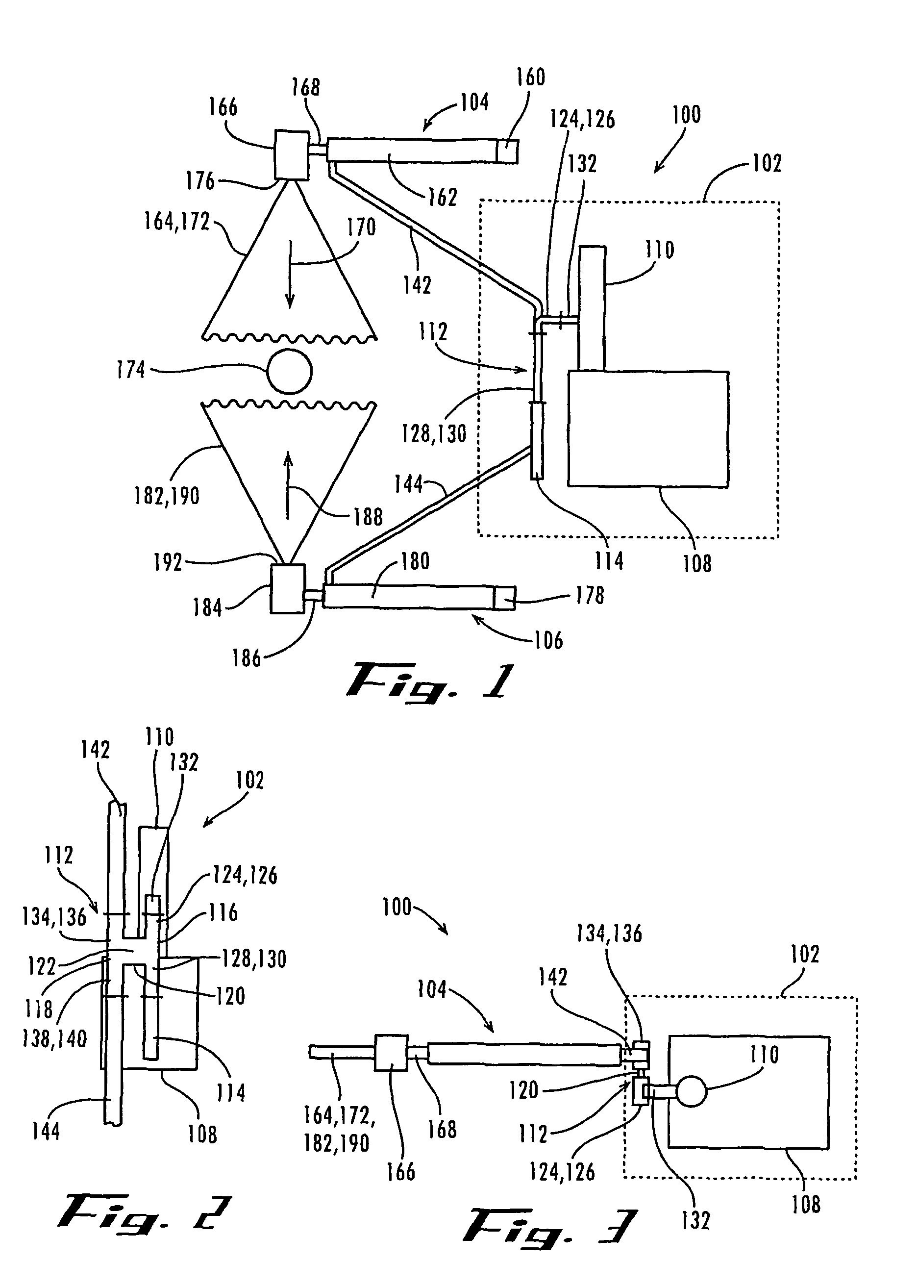
[0018]Referring now to the drawings in which like numerals represent like elements or steps throughout the several views, FIG. 1 displays a top, plan pictorial view of a radiation system 100 forming part of a radiation treatment system for treating subject objects by irradiating them from different directions according to a first exemplary embodiment of the present invention. The radiation system 100 comprises a single RF drive subsystem 102, a first RF electron accelerator 104, and a second RF electron accelerator 106. The RF drive subsystem 102, importantly, includes a single power supply 108 and a single RF generator 110 connected to an output of the power supply 108 for the receipt of power therefrom. The RF drive subsystem 102 also includes a 3 dB directional coupler 112 connected between the RF generator 110 and the RF electron accelerators 104, 106 and a waveguide load 114. In a form acceptable in accordance with the first exemplary embodiment, the RF generator 110 comprises ...


PUM


Abstract

Radiation systems, including apparatuses and methods, for providing multiple independent RF electron accelerators with RF power from a single RF generator. The radiation systems may be employed in radiation treatment systems for treating subject objects by irradiating them from different directions and in inspection systems for producing images of the contents of a container or other volume in multiple planes using RF electron accelerators that receive RF electromagnetic power from a single RF generator. The radiation systems include RF drive subsystems each having a 3 dB directional coupler connected between an RF generator and RF electron accelerators. Each 3 dB directional coupler divides RF electromagnetic power received from the RF generator into equal or unequal portions for delivery to respective RF electron accelerators.

Description

CROSS-REFERENCE TO RELATED APPLICATION[0001]This application claims the benefit of priority to U.S. provisional application Ser. No. 60 / 498,394, which is entitled “RADIATION SYSTEM” and was filed on Aug. 27, 2003.FIELD OF THE INVENTION[0002]The present invention relates, generally, to the field of particle accelerators and, in its exemplary embodiments, to the field of radiation systems having radio frequency (RF) electron accelerators that form a part of radiation treatment systems, inspection systems, or other systems in which the irradiation of subject objects from multiple directions or in multiple planes is beneficial.BACKGROUND OF THE INVENTION[0003]Radio frequency (RF) electron accelerators are sometimes employed in radiation treatment systems that are used to sterilize medical instruments and materials, pasteurize and disinfest food products, and decontaminate harmful waste. Similarly, RF electron accelerators may be employed in inspection systems for inspecting vehicles, ca...

Claims


Application Information

Patent Timeline
Patent Type & Authority Patents(United States)
IPC IPC(8): H05H9/00G21G5/00G21KH01J23/00
CPCH05H15/00H05H7/02
Inventor ZAVADLSEV, ALEXANDRE A.BOWSER, GARY F.
Owner SCANTECHIBS IP HLDG
Learn More