Center shifted roll forming

a center-shifted, roll-forming technology, applied in the direction of rolling mill control devices, manufacturing tools, metal rolling arrangements, etc., can solve the problems of inability to produce more complex shapes in modern industry, limited device shapes that can be produced, etc., to achieve quick and economical production

Inactive Publication Date: 2007-06-07
MCGUSHION KEVIN DAVID JR
View PDF11 Cites 1 Cited by
  • Summary
  • Abstract
  • Description
  • Claims
  • Application Information

AI Technical Summary

Benefits of technology

[0008] In accordance of the present invention, a roll forming machine capable of quickly and economically producing complex curvilinear patterns in malleable materials is provided. The present invention further provides a device that can produce a bending radius that is approximately equal to or greater than the forming mandrel. The present invention again further provides a device that can be programmed to bend a complex series of radii or planar sections along a material.

Problems solved by technology

These devices are limited in the shapes that can be produced.
More complex shapes required in modern industry are not possible with current roll forming means
With either choice of material, the construction of a structural member with a curvilinear web is a challenge, in maintaining quality, tolerances, and minimizing costs.

Method used


Image

  • Center shifted roll forming
  • Center shifted roll forming
  • Center shifted roll forming

Examples


Embodiment Construction

[0033] The detailed description set forth below in connection with the appended drawings is intended as a description of presently-preferred embodiments of the invention and is not intended to represent the only forms in which the present invention may be constructed and / or utilized. The description sets forth the functions and the sequence of steps for constructing and operating the invention in connection with the illustrated embodiments. However, it is to be understood that the same or equivalent functions and sequences may be accomplished by different embodiments that are also intended to be encompassed within the spirit and scope of the invention.

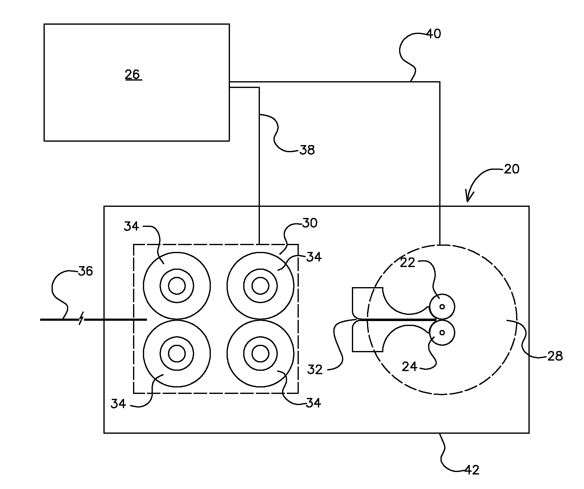
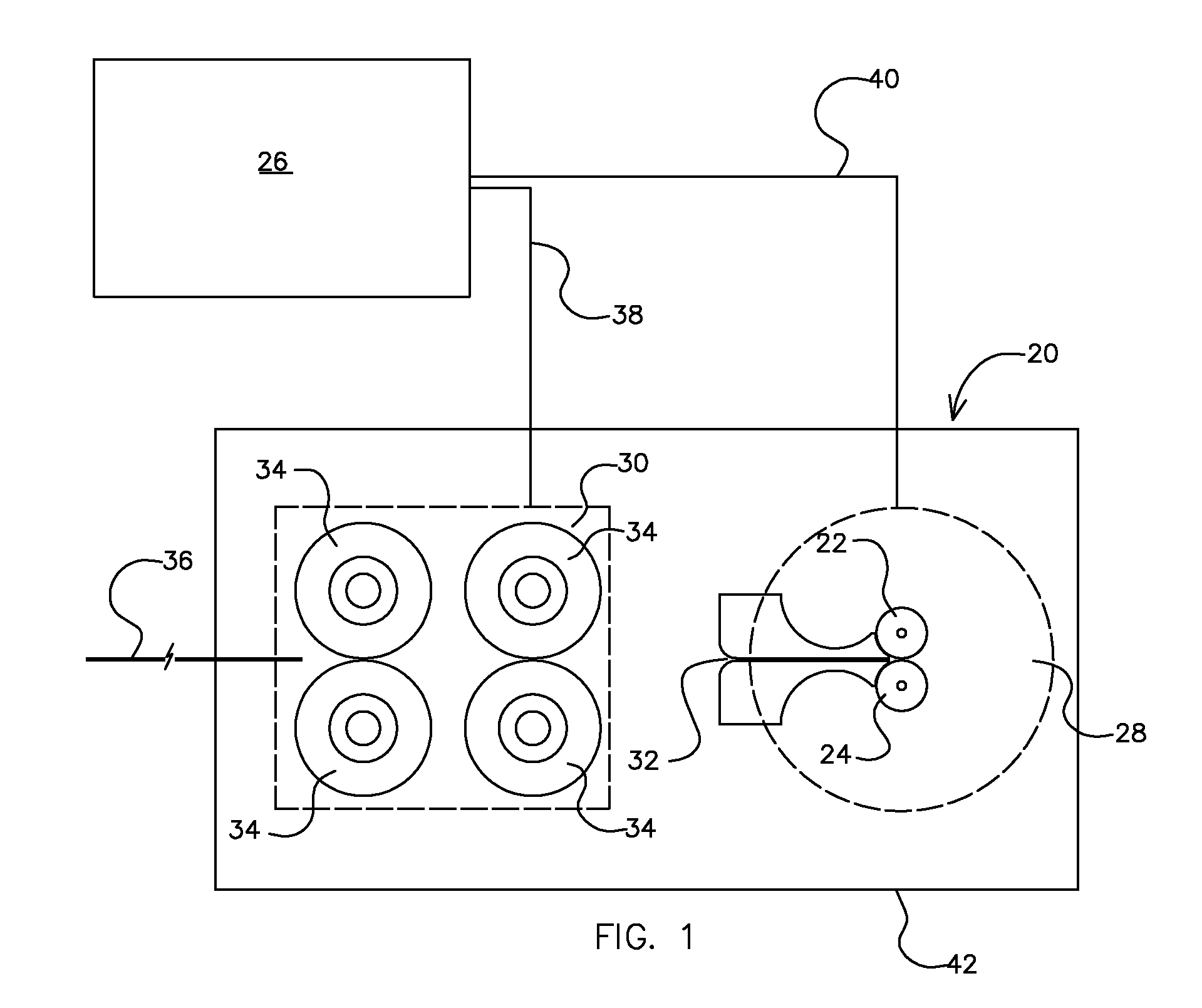
[0034] Looking at FIG. 1, the mechanical setup of a roll form machine (20) that is compatible with the preferred embodiment of the present invention is shown. The first cylinder (22) and the second cylinder (24) are in a home position, where neither are selected as the forming tool, and both are in the hoe position with zero angular d...


PUM

PropertyMeasurementUnit
feed rateaaaaaaaaaa
angular displacementaaaaaaaaaa
radiusaaaaaaaaaa

Abstract

The present invention provides a bending machine for strip, webbing, or rod material comprising: an electronic control means; two cylinders, each acting selectively as a forming mandrel or a forming tool; an angular displacement means, controlling the orbit of the forming mandrel; and a feeding means, controlling the rate of material advancement; wherein a curvilinear profile of varying radii is formed in at least a portion of a material by varying the feed rate and the angular displacement, individually or in conjunction.

Description

CROSS-REFERENCE TO RELATED APPLICATIONS [0001] This is a continuation-in-part of application Ser. No. 10 / 896,257, filed Jul. 21, 2004, now abandoned.BACKGROUND OF THE INVENTION [0002] This invention relates generally to an improved roll forming mechanism. And, more particularly, this invention relates to the forming of malleable materials, such as tubes, strips, sheets, webbing, and similar materials into a curvilinear profile, using a roll form machine known to industry, wherein two parallel cylinders selectively act as both a forming mandrel and a forming tool. [0003] As designs in numerous industries become more organic and irregular, having non-repeating patterns and complex shapes (designed to increase strength, increase beauty, maximize performance, or provide clearance), devices are required to form these complex shapes and underlying frameworks. Industries employing these complex design profiles include the aerospace, construction, process industries, and many others. [0004]...

Claims


Application Information

Patent Timeline
Patent Type & Authority Applications(United States)
IPC IPC(8): B21B37/24
CPCB21D7/08
Inventor MCGUSHION, KEVIN DAVID JR.
Owner MCGUSHION KEVIN DAVID JR
Why Eureka
Try Eureka