[0038] While the present invention is susceptible of embodiment in various forms, there is shown in the drawings and will hereinafter be described a presently preferred embodiment with the understanding that the present disclosure is to be considered an exemplification of the invention and is not intended to limit the invention to the specific embodiments illustrated.
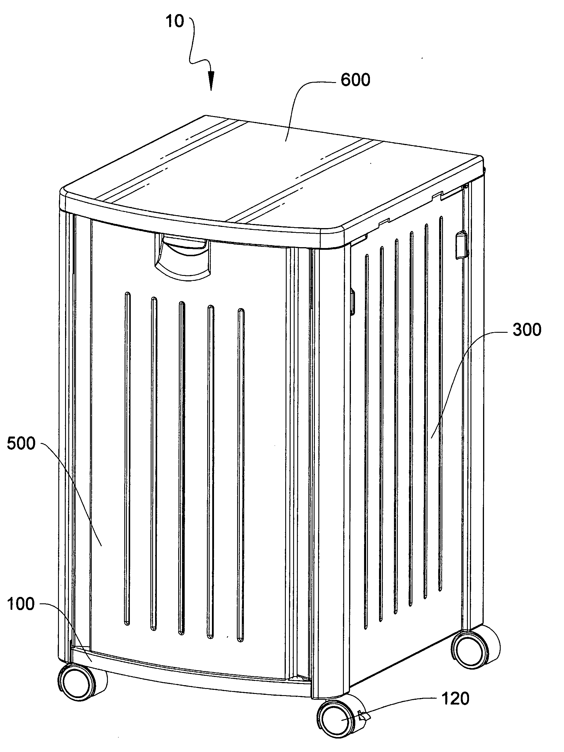
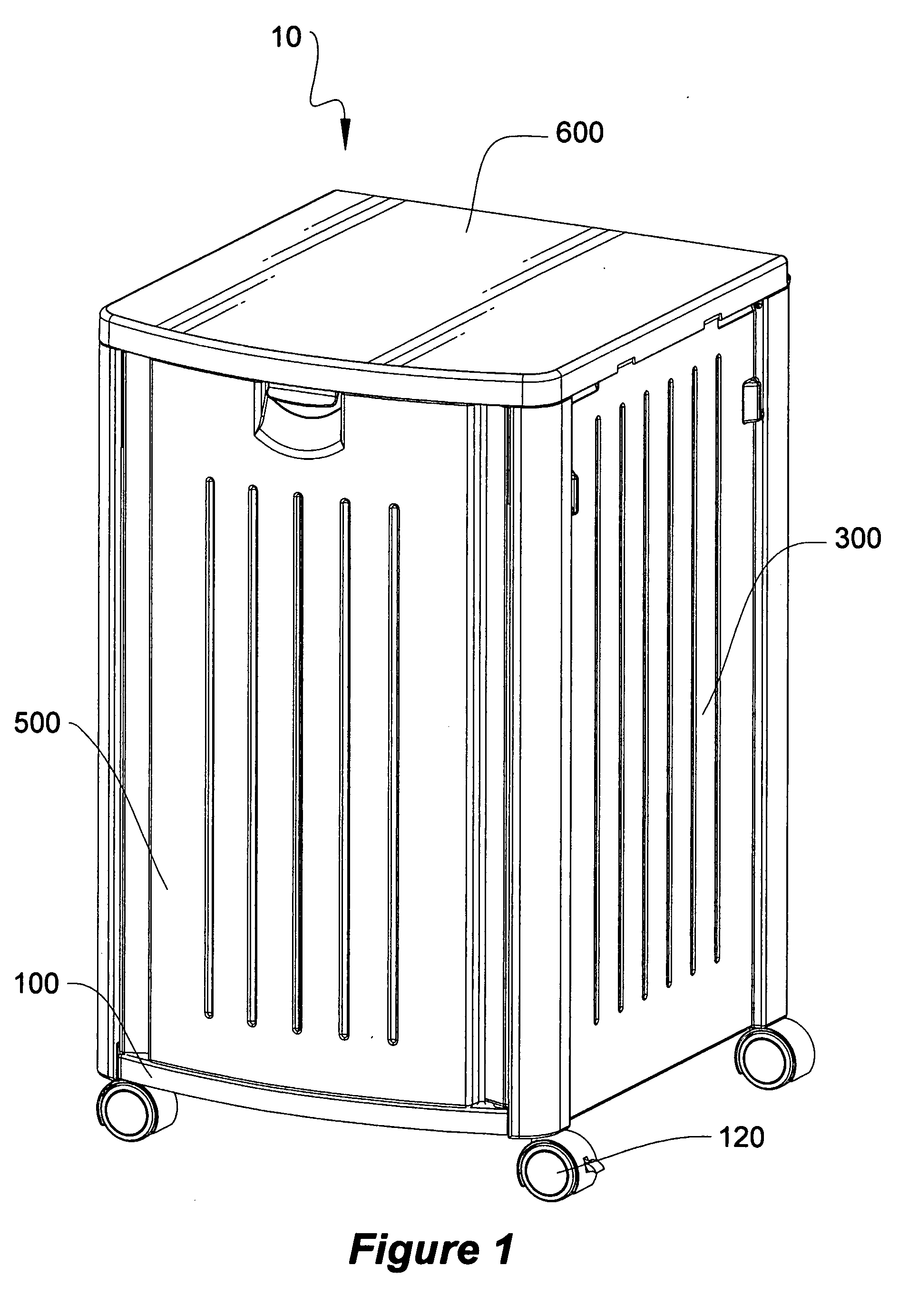
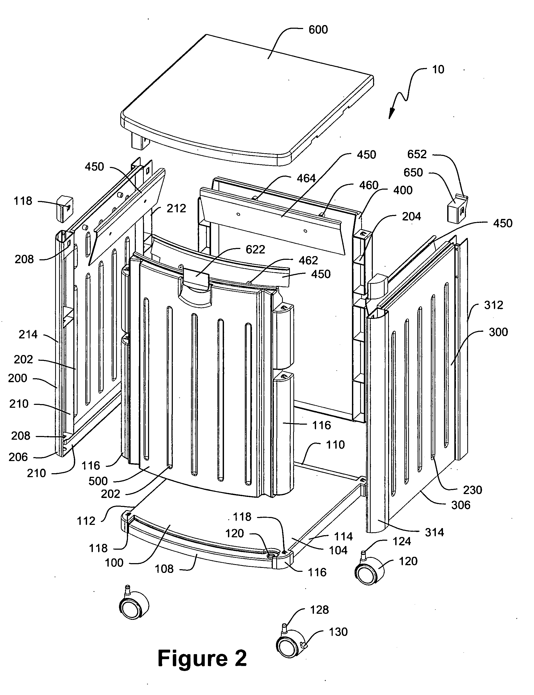
[0039]FIGS. 1-2 which are now referenced illustrate perspective and exploded views of the trash container assembly, generally referenced as 10, according to a preferred embodiment of the present invention. The trash container is made up of a base panel 100, left side wall panel 200, right side wall panel 300, back wall panel 400, front wall panel 500 and cover panel 600. In the preferred embodiment the panels comprising the assembly are formed of but not limited to a suitable plastic such as polystyrene, polypropylene or polyethylene, through the process of injection molding. The result is that the panels comprising the trash container 10 are formed as unitary single wall panels with integral connectors and cross bracing. Strengthening ribs 202 and gussets 204 are formed within the inner surfaces of the wall panels, cover panel, and base panel in order to enhance rigidity of the panels while leaving the external surface in a generally smooth condition for aesthetic purposes, as shown in FIG. 2. The base panel 100 has a top surface 104, bottom surface 106 (FIG. 7), front edge 108, back edge 110, left edge 112, and right edge 114. Integrally formed along the left and right base panel edges is a plurality of bosses 116 for attaching the base panel to the left 200 and right 300 wall panels. The bosses 116 extend outwardly from each edge to cooperate with sockets 210 extending inwardly along the bottom portions 206, 306 of the left and right wall panels respectively. The bosses 116 and sockets 210 are constructed and arranged so that the bosses 116 enter and mateably engage the sockets 210, securing the panels together in an inter-fitting engagement and perpendicular arrangement. Detent or spring-lock fasteners, such as those illustrated at 118 cooperate with apertures 208, to secure the bosses 116 to the sockets 210. Those skilled in the art will appreciate that the spring-lock fasteners 118 can be used throughout the trash container 10 to mount or secure components to one another, and to facilitate ready assembly of the trash container if it is provided in an unassembled or broken-down condition. The overlapping boss 116 and socket 210 arrangement increases the structural integrity of the trash container 10 by preventing the panels 200, 300, 400, 500 from bowing or bending inwardly or outwardly, and thus, adversely affecting the appearance or operation of the trash container 10.
[0040] The left wall panel 200 is configured having a first edge 212 and a second edge 214. Both edges 212, 214 include integrally formed elongated and contoured sockets 210 extending inwardly in a linear fashion along each edge. The sockets 210 are generally constructed and arranged to cooperate with the bosses 116 provided along either edge of the back panel 400 and front panel 500.
[0041] The right wall panel 300 is configured having a first edge 312 and a second edge 314. Both edges 312, 314 include integrally formed elongated and contoured sockets 210 extending inwardly in a linear fashion along each edge. The sockets 210 are generally constructed and arranged to cooperate with bosses 116 provided along either edge of the back panel 400 and front panel 500.
[0042] The outer surface of the panels 200, 300, 400, 500 are constructed generally smooth having a plurality of inwardly bowed grooves 230 for added strength and aesthetic appearance. The inside of the panels 200, 300, 400, 500 are constructed with a plurality of strengthening ribs 202 extending along the panels with a portion of the ribs 202 being provided with a plurality of gussets 204 to further strengthen the panels. The ribs 202 and gussets 204 increase the structural integrity of the trash container 10 by preventing the panels 200, 300, 400, 500 from bowing or bending inwardly or outwardly, and thus, adversely affecting the appearance or operation of the trash container 10. The integrally formed ribs 202 and gussets 204 are facilitated by injection molding. Injection molding offers significant strength and stability advantages over blow-molding or rotational molding as utilized in the prior art. In this manner the container of the instant invention is capable of handling a significant amount of weight as compared to prior art plastic trash containers.
[0043] The left and right side panels 200, 300 are attached to the base panel 100 by inserting the contoured bosses 116 into the sockets 210 until the spring tabs 118 engage the apertures 208 in the sockets 210 of the left 200 and right 300 panels.
[0044] The front and back panels 400, 500 are attached to the left 200 and right 300 panels by inserting the elongated and contoured bosses 116 into sockets 210 until the spring tabs 118 integrally formed into the contoured bosses 116 engage the apertures 208 in the sockets of the left and right panels 400, 500. It will be appreciated that the purpose of the contoured and elongated bosses 116 are to align two panels in a perpendicular relationship and to facilitate their mechanical connection. The perpendicular panels are brought into an overlapping relationship wherein the contoured bosses 116 enter the corresponding sockets 210 in the left, and right panels 200, 300 respectively. The result is a mechanically secure connection between the panels. The overlapping edges between the panels as described above provides a secure connection and offers several advantages. First, the design allows the panels to be connected without the need for separate connectors. Second, the design creates a positive lock that prevents separation of the panels. Third, the design maintains alignment of the panels in the same plane and prevents bowing or bending of either panel relative to one another. The resultant trash container created by the combination of the interlocking panels benefits from high structural integrity and reliable operation.
[0045] Referring to FIGS. 3-6, perspective and section views of the trash container are shown illustrating the pivotal operation of the cover panel 600 and latch assembly. Also illustrated is the construction and arrangement of the separable and replaceable hinge assemblies. The hinge assemblies generally include a pair of hinge inserts 650 (FIG. 2), each having a pair of hinge pins 652. The hinge pins are constructed and arranged to cooperate with a plurality of hinge pin receivers 602. The hinge pin receivers 602 are generally a pair of outwardly depending supports 603 located adjacent to the back edge 610 of the cover panel 600 and are constructed and arranged to cooperate with a hinge pin 652 to allow pivotal movement of the cover panel 600 between an open position illustrated in FIG. 3 and a closed position illustrated in FIG. 1. The hinge pins 652 are each integrally formed onto the upper portion of the hinge inserts 650. The hinge pins 652 cooperate with their respective hinge pin receivers 602 to allow pivotal movement of the cover panel 600 and also allow the cover 600 to be removed when in the open position by lifting the cover upward and sliding the hinge pin receiver 602 outward from the pins 652. The cover panel 600 is releasably secured in the closed position by pivoting the cover panel downward until the cover latch 622 pivotally mounted into the front panel 500 engages at least one corresponding indentation 620 formed in the front portion of the cover panel 600. The result is a positive mechanical connection. To open the cover panel 600, the cover latch 622 is pulled outward until the catch 624 is released from the indentation 620 and the cover panel is pivoted upwards. The result is a positive mechanical connection between the side walls of the container and the cover panel 600 that resists opening by winds or animals, and yet provides easy access for placing trash into the container.
[0046] It should be appreciated that the hinge assemblies allow the cover panel 600 to be installed and/or removed when the cover 600 is in the open position and yet the cover and lid are secure and non-removable when in the closed position. It should also be appreciated that the hinge inserts are removable and replaceable in the event that one or both should become damaged.
[0047] Referring to FIGS. 2-6 the retainer-ramps 450 are illustrated. The retainer-ramps include an upper portion 452 that is constructed and arranged to retain a flexible liner 700 in an open position within the trash container and a lower portion 454 constructed and arranged to permit a filled liner to be easily removed from the trash container without catching or snagging. The upper portion of the retainer-ramp includes a depending lip 456 over which the flexible liner may be folded over for retention thereof. The lowermost portion of retainer-ramp is constructed and arranged to fit against the inner surface of each respective panel and taper inwardly away from the inner surface as the retainer-ramp extends toward the container opening. In this manner the retainer-ramps function as a guide to aid in the removal of a filled liner from the container. The inner surface of the retainer-ramp 458 includes an attachment means integrally formed thereto for attaching the retainer-ramp to the inner surface of the front, back, left and right panels. The attachment means is illustrated herein as a pair of snap-lock connectors 460. The snap-lock connectors each include an inner portion 462 and an outer portion 464; both portions are integrally formed onto their respective panels. For assembly the inner portion is pressed into the outer portion until the components are engaged. In addition to the retainer-ramps the base panel is provided with a vent aperture 120 to aid in the removal of filled liners.
[0048] Referring to FIGS. 2 and 7, the casters 120 and caster bosses 122 are illustrated. The casters 120 include a stem 124 that is constructed and arranged to cooperate with an aperture 126 integrally formed onto the lower surface 106 of the base panel 100. For assembly the stem is inserted into the boss aperture until retainer ring 128 snaps into a corresponding groove formed into the aperture, the result is a mechanically secure connection. The casters may also include a releasable lock 130 to prevent the trash container from unwanted movement on hills and the like.
[0049] All patents and publications mentioned in this specification are indicative of the levels of those skilled in the art to which the invention pertains. All patents and publications are herein incorporated by reference to the same extent as if each individual publication was specifically and individually indicated to be incorporated by reference.
[0050] It is to be understood that while a certain form of the invention is illustrated, it is not to be limited to the specific form or arrangement herein described and shown. It will be apparent to those skilled in the art that various changes may be made without departing from the scope of the invention and the invention is not to be considered limited to what is shown and described in the specification.
[0051] One skilled in the art will readily appreciate that the present invention is well adapted to carry out the objectives and obtain the ends and advantages mentioned, as well as those inherent therein. The embodiments, methods, procedures and techniques described herein are presently representative of the preferred embodiments, are intended to be exemplary and are not intended as limitations on the scope. Changes therein and other uses will occur to those skilled in the art which are encompassed within the spirit of the invention and are defined by the scope of the appended claims. Although the invention has been described in connection with specific preferred embodiments, it should be understood that the invention as claimed should not be unduly limited to such specific embodiments. Indeed, various modifications of the described modes for carrying out the invention which are obvious to those skilled in the art are intended to be within the scope of the following claims.