Automatic Doorbell Driver

a doorbell and automatic technology, applied in the field of doorbell systems, can solve the problems of preventing their widespread application, requiring periodic maintenance, expensive, and/or difficult to install, and achieve the effects of reducing the number of automatic doorbells

Active Publication Date: 2007-06-07
LANGER PETER +1
View PDF13 Cites 91 Cited by
  • Summary
  • Abstract
  • Description
  • Claims
  • Application Information

AI Technical Summary

Benefits of technology

[0007] The present invention is an automatic doorbell driver that is a perfect drop-in replacement device for a pushbutton of a conventional doorbell system and which upon installation converts a conventional doorbell system into an automatic doorbell system.
[0008]FIG. 1 is a schematic block diagram of a conventional doorbell system utilizing a pushbutton.
[0009]FIG. 2 is a schematic block diagram of an automatic doorbell system utilizing an automatic doorbell driver according to the present invention.
[0010]FIG. 3 is a schematic block diagram of the automatic doorbell system shown in FIG. 2 including the major components of the automatic doorbell driver.
[0011]FIG. 4 is an electrical schematic of the automatic doorbell system shown in FIG. 3.
[0012]FIG. 5 is an electrical schematic of an automatic doorbell system utilizing an alternate embodiment of an automatic doorbell driver according to the present invention.

Problems solved by technology

Unfortunately, all of the systems devised thus far, including Calvin's and von Bauer's, have a significant disadvantage that has prevented their widespread application.
That is, they are either independent or predominately independent systems that do not, or do not sufficiently, interface with or complement a conventional doorbell system.
As a result, they are complex, difficult to install, expensive, redundant, and / or require periodic maintenance (e.g., battery replacement)

Method used


Image

  • Automatic Doorbell Driver
  • Automatic Doorbell Driver
  • Automatic Doorbell Driver

Examples


first embodiment

Operation of

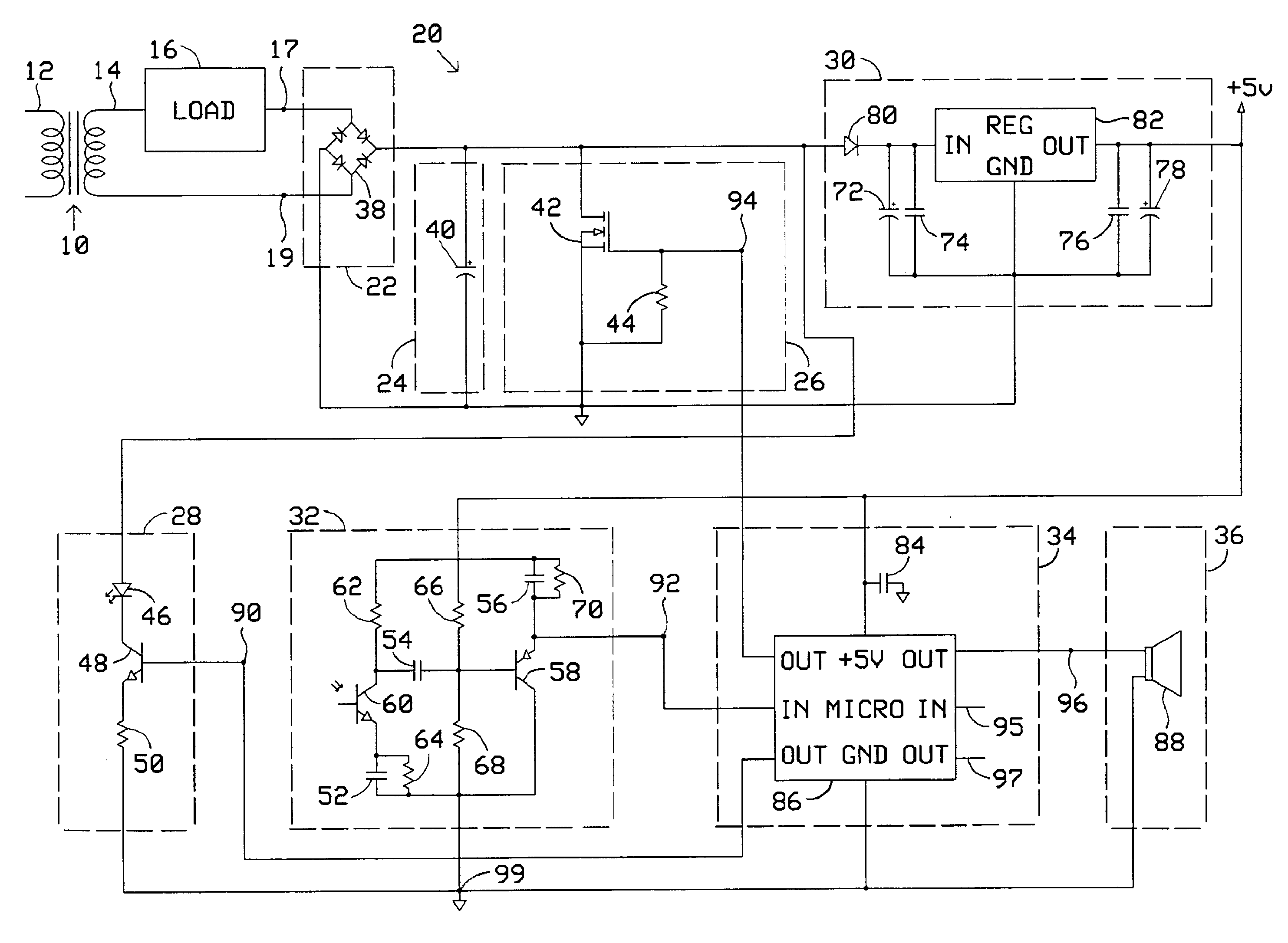
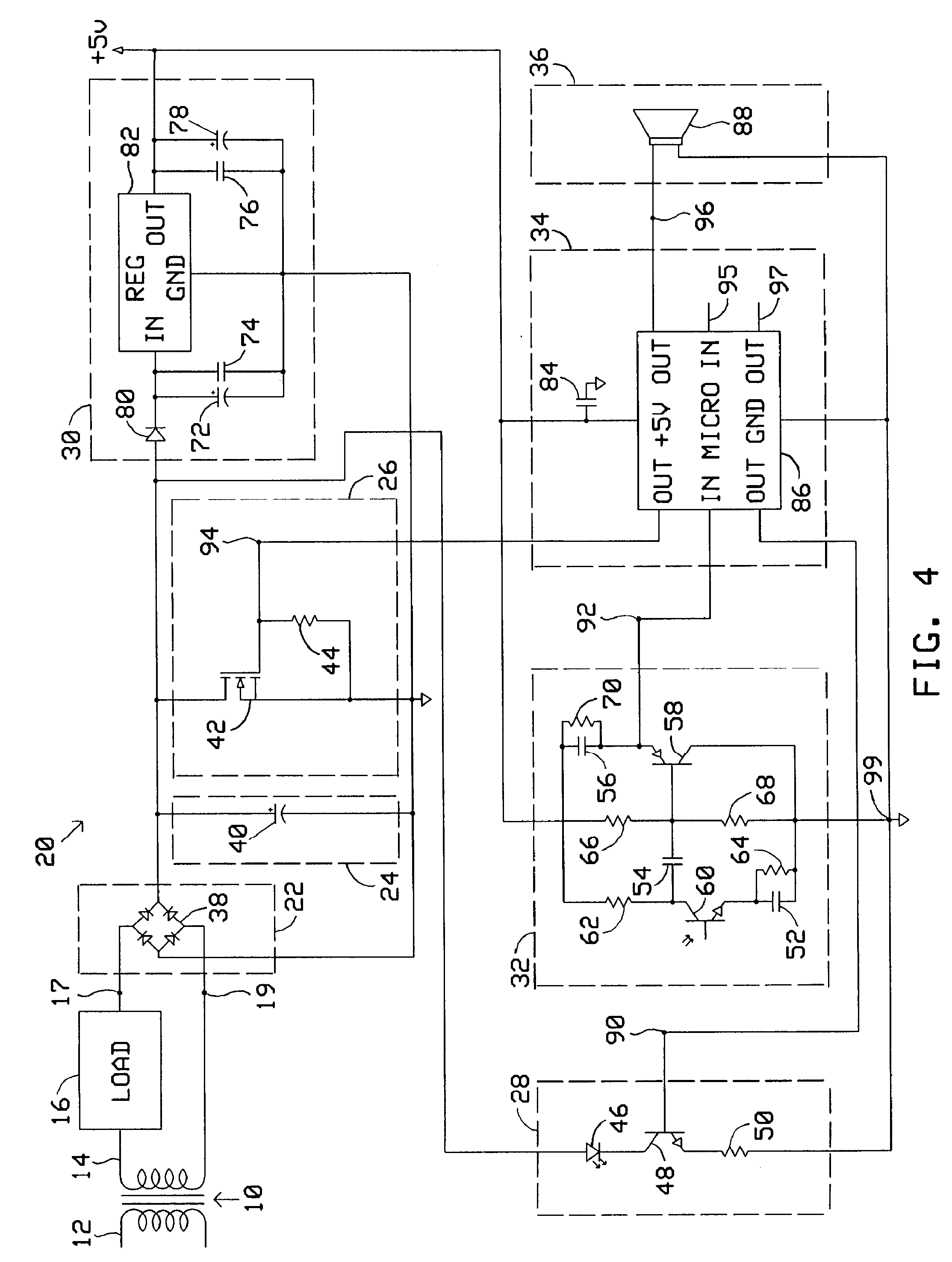
[0018] Operation of automatic doorbell driver 20 comprises three phases; a sensing phase, an activation phase, and a feedback phase.

[0019] During the sensing phase, microprocessor 86 provides a pulsed voltage above a threshold level at node 90 thereby intermittently turning on transistor 48 and diode 46 causing diode 46 to emit pulsed light toward a proximity zone outside a building's doorway. When an object, such as a person, enters the proximity zone, the pulsed light is reflected off the object and is thereupon sensed by phototransistor 60 which in conjunction with capacitor 52 and resistors 62, 64 operates as an inverting amplifier configured to provide unity DC gain and high AC gain. This configuration ensures that the amplifier is most responsive to pulsed light emitted from diode 46 and least responsive to steady state light emitted from other sources such as incandescent light or daylight. The sensed reflected pulsed light off the approaching person results in a...

second embodiment

Operation of

[0028] Like the previous embodiments, operation of the alternate embodiment comprises three phases; a sensing phase, an activation phase, and a feedback phase. During the sensing phase, operation is identical to that of the previous embodiments.

[0029] During the activation phase, microprocessor 86 provides a voltage above a threshold level at node 116 causing current to flow through resistors 108 and 110 resulting in a corresponding voltage above a threshold level at the base of transistor 100 thereby turning on transistor 100. Resistor 108 limits the current at the base of transistor 100. Pull-down resistor 110 ensures that leakage current does not inadvertently turn on transistor 100. When transistor 100 is on, current flows through resistors 104, 106, and Zener diode 114 resulting in a voltage below a threshold level at the base of transistor 102 thereby turning on transistor 102. Pull-up resistor 104 ensures that leakage current does not inadvertently turn on transi...

third embodiment

Operation of

[0032] Operation of this embodiment is identical to that of the previous embodiments with the exception that during the activation phase, primary load 16 utilizes the stepped down household AC voltage coupled to it when MOSFET 42 or MOSFET 98 is turned on as a trigger rather than to directly produce a desired sound. When primary load 16 detects the trigger, it energizes an internal sound device. The sound device can remain energized indefinitely, even after the activation phase ends, due to the constant source of power provided by the added diode.


PUM


Abstract

An automatic doorbell driver that utilizes the power, wiring, and primary load of a conventional doorbell system. The automatic doorbell driver comprising coupling means for coupling the automatic doorbell driver to the conventional doorbell system; power supply means for supplying power to the automatic doorbell driver; sensing means for sensing an object in a proximity zone; and switching means responsive to the sensing means for coupling power to, and thereby controlling the energization and de-energization of, the primary load of the conventional doorbell system; whereby the automatic doorbell driver can easily convert the conventional doorbell system into an automatic doorbell system.

Description

CROSS-REFERENCE TO RELATED APPLICATIONS [0001] This application claims the benefit of U.S. Provisional Patent Application Ser. No. 60 / 741,746, filed Dec. 2, 2005.BACKGROUND OF THE INVENTION [0002] This invention relates generally to doorbell systems and particularly to an automatic doorbell driver that utilizes the power, wiring, and primary load of a conventional doorbell system. [0003] Conventional doorbell systems in buildings, typically residences, throughout the United States and elsewhere are hardwired and comprise a transformer, a primary load, and a pushbutton. The transformer lowers standard household AC voltage to a level required to operate the primary load. The primary load is an electromagnetic or electronic sound device that operates on low voltage and is typically a bell, buzzer, or chime. The pushbutton is a typically a normally open switch. System activation requires physical contact with the pushbutton. Manual depression of the pushbutton closes an electrical circu...

Claims


Application Information

Patent Timeline
Patent Type & Authority Applications(United States)
IPC IPC(8): G08B13/00G08B3/00
CPCG08B3/10
Inventor LANGER, PETERCINZORI, DOUGLAS CARL
Owner LANGER PETER
Why Eureka
Try Eureka