Image capture apparatus and zoom lens

a technology of image capture and zoom lens, which is applied in the field of image capture apparatus and zoom lens, can solve the problems of unfavorable folding length of the lens barrel, inability to obtain high-quality images in terms of noise, and large-sized and heavyweight, and achieves high image quality, high image quality, and high image quality

Inactive Publication Date: 2007-06-07
SONY CORP
View PDF9 Cites 107 Cited by
  • Summary
  • Abstract
  • Description
  • Claims
  • Application Information

AI Technical Summary

Benefits of technology

[0010] As mentioned previously, if a compact digital camera with a zoom lens is miniaturized by the adoption of a small-sized imager device, high quality images cannot be obtained in terms of noise, grayscale representation or the like, but if high image quality is pursued, an interchangeable lens type of camera is needed which becomes large-sized and heavyweight when a zoom lens is attached thereto. In the market, there is still a strong demand for a compact digital camera with a zoom lens which is a cross between a compact digital camera and a single-lens reflex camera, thereby maintaining high image quality by adopting an imager device having a sufficient size to obtain the high image quality.

Problems solved by technology

As mentioned previously, if a compact digital camera with a zoom lens is miniaturized by the adoption of a small-sized imager device, high quality images cannot be obtained in terms of noise, grayscale representation or the like, but if high image quality is pursued, an interchangeable lens type of camera is needed which becomes large-sized and heavyweight when a zoom lens is attached thereto.
However, the folding optical system is essentially a technique which increases the volume of a lens itself, and if a lens system is proportionately enlarged in accordance with a large screen size in a compact camera which is to be realized in combination with an imager device of small screen size, the folded length of a lens barrel unpreferably becomes so long as to hinder the use of the camera.
The means disclosed in Patent Literatures 2 and 3 are useful as means for reducing the folded length of a lens barrel, but since two movable lens groups are not present on one optical axis (which is not folded halfway), an eccentric error easily occurs between the two movable lens groups and measurement and adjustment of the eccentric error are extremely difficult, so that it is difficult to carry out mass-production while maintaining stable performance.
In addition, if the folded length of the lens barrel is reduced by the means disclosed in Patent Literatures 2 and 3, there may be an issue such that the dimension of a package containing an imager device of large screen size hinders a reduction in the thickness of the camera.

Method used


Image

  • Image capture apparatus and zoom lens
  • Image capture apparatus and zoom lens
  • Image capture apparatus and zoom lens

Examples


first embodiment

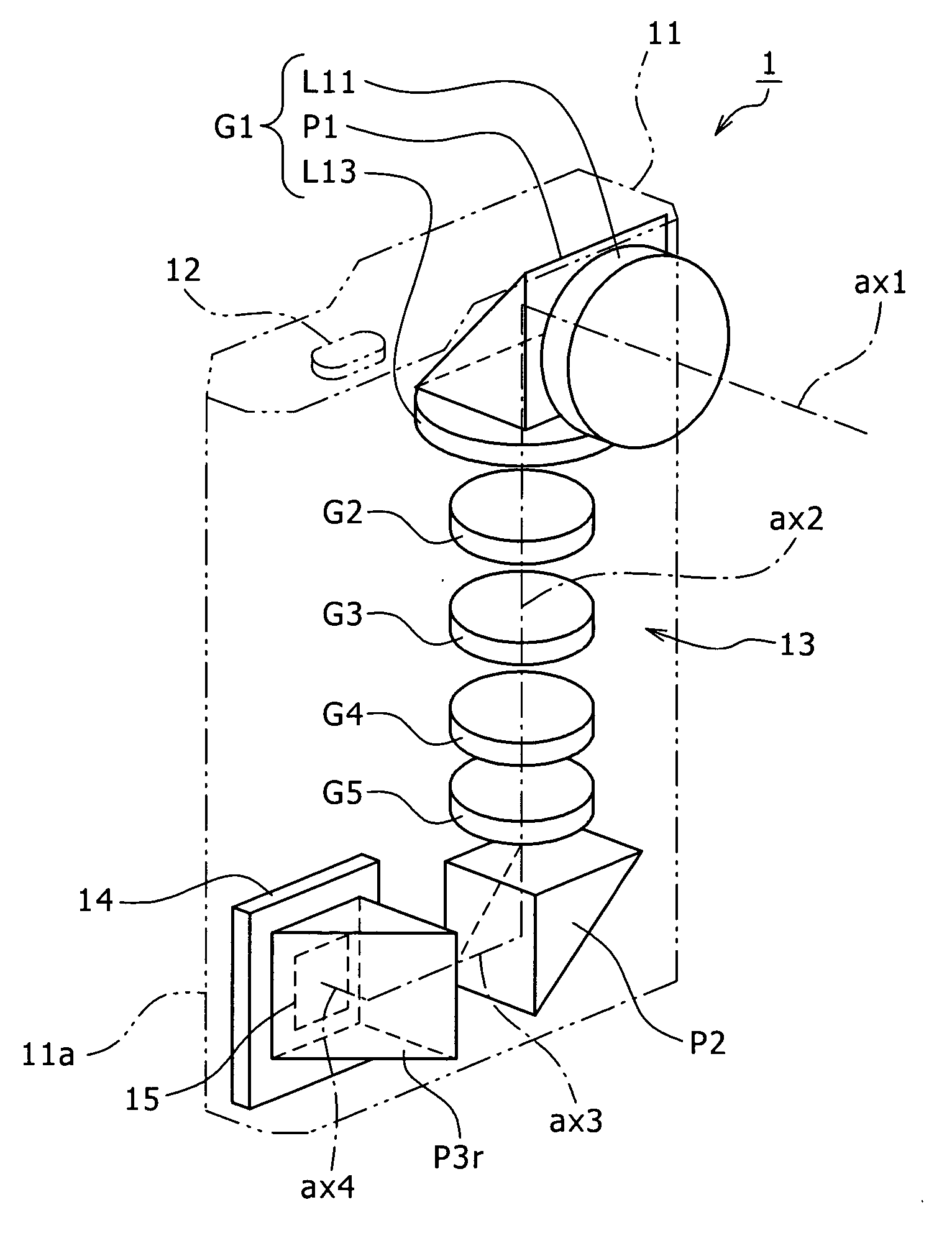
[0047] The construction of the optical system 13 in the image capture apparatus 1 will be described below with reference to FIG. 1. The zoom lens 13 includes, in the following order from an object side, the first lens group G1 which is made of a negative lens group L11 having the first optical axis (the entrance optical axis) ax1, the first prism P1, and a positive lens group L13 having a second optical axis ax2 folded downward approximately 90 degrees by the prism P1, a second lens group G2 (corresponds to the movable lens group) which has negative refractive power and moves along the optical axis to mainly perform a zooming action, a third lens group G3 (corresponds to the fixed lens group) which is fixed on the optical axis and has positive refractive power, a fourth lens group G4 (corresponds to the fixed lens group) which has positive refractive power and performs focusing as well as correction of variations of an image forming position due to power variations, and a fifth len...

second embodiment

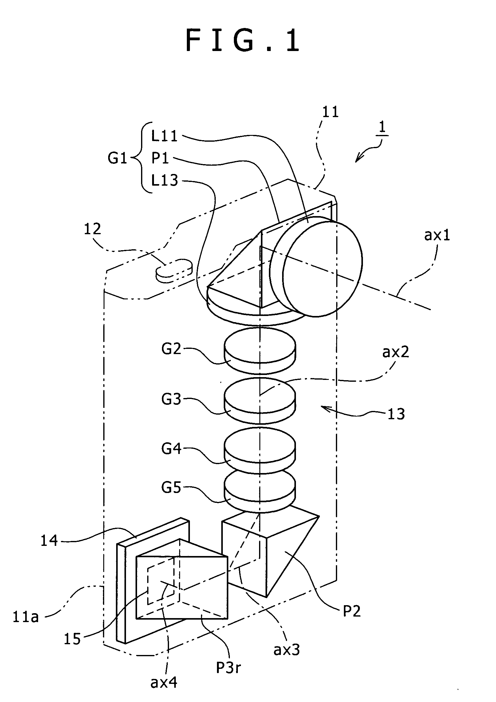
[0049] The construction of the optical system 23 in the image capture apparatus 2 will be described below with reference to FIG. 2. The zoom lens 23 includes, in the following order from the object side, the first lens group G1 which is made of the negative lens group L11 having the first optical axis (the entrance optical axis) ax1, the first prism P1, and the positive lens group L13 arranged on the second optical axis ax2 folded laterally approximately 90 degrees by the prism P1, the second lens group G2 which has negative refractive power and moves along the optical axis to mainly perform a zooming action, the third lens group G3 which is fixed on the optical axis and has positive refractive power, the fourth lens group G4 which has positive refractive power and performs focusing as well as correction of variations of an image forming position due to power variations, and the fifth lens group G5 which is fixed on the optical axis and has negative refractive power, the second len...

third embodiment

[0051] The construction of the optical system 33 in the image capture apparatus 3 will be described below with reference to FIG. 2. The zoom lens 33 includes, in the following order from the object side, the first lens group G1 which is made of the negative lens group L11 having the first optical axis (the entrance optical axis) ax1, the first prism P1, and the positive lens group L13 arranged on the second optical axis ax2 folded laterally approximately 90 degrees by the prism P1, the second lens group G2 which has negative refractive power and moves along the optical axis to mainly perform a zooming action, the third lens group G3 which is fixed on the optical axis and has positive refractive power, the fourth lens group G4 which has positive refractive power and performs focusing as well as correction of variations of an image forming position due to power variations, and the fifth lens group G5 which is fixed on the optical axis and has negative refractive power, the second len...


PUM


Abstract

An image capture apparatus includes: a zoom lens arranged in a housing and including fixed lens groups, movable lens groups and at least three prisms; and an imager device arranged in the housing. The zoom lens includes: a fixed first lens group including a negative lens group having a first optical axis, a first prism approximately perpendicularly folding an optical axis, and a positive lens group having a second optical axis folded by the first prism; movable lens groups and at least one fixed lens group arranged along the second optical axis to perform a zooming action, an image plane position correcting action and a focusing action; and a second prism arranged on an image side relative to a movable lens group that is a closest to the image side among the plurality of movable lens groups for approximately perpendicularly folding the optical axis.

Description

BACKGROUND OF THE INVENTION [0001] 1. Field of the Invention [0002] The present invention relates to an image capture apparatus and zoom lens, and more particularly to a zoom lens having optical-axis folding means and an image capture apparatus using such a zoom lens, and to techniques capable of compatibly realizing an increase in the size of an imager device of a digital camera and a reduction in the thickness of the digital camera. [0003] 2. Description of Related Art [0004] In recent years, digital cameras have exceeded film cameras in annual sales and have spread at a remarkable pace. Commercially popular types of digital cameras, particularly so-called digital compact cameras, are small-sized, lightweight, and low in running cost compared to compact film cameras, and allow users to confirm captured results on their liquid crystal display screens immediately after each image capture. This is considered to be the reason why digital compact cameras have spread. [0005] A critical ...

Claims


Application Information

Patent Timeline
Patent Type & Authority Applications(United States)
IPC IPC(8): G02B13/16
CPCG02B5/04G02B15/177H04N5/2254G02B15/145115G02B7/04G02B15/145113G02B13/009G02B3/0087G02B3/0062G03B17/12G02B2003/0093H04N23/55
Inventor NANJO, YUSUKE
Owner SONY CORP
Why Eureka
Try Eureka