Magnetoresitive sensor having an enhanced lead overlay design and shape enhanced pinning

a technology of lead overlay and magnetoresitive sensor, which is applied in the field of magnetoresitive sensor construction, can solve the problems of inability to adequately pin the pinned layer by current pinning mechanism, the pinned layer becomes impracticably unstable, and the future generation of sensors will be so small, so as to improve the sensor performance, enhance the pinning strength, and enhance the pinning

Inactive Publication Date: 2007-06-07
WESTERN DIGITAL TECH INC
View PDF4 Cites 13 Cited by
  • Summary
  • Abstract
  • Description
  • Claims
  • Application Information

AI Technical Summary

Benefits of technology

[0016] The present invention provides a magnetoresistive sensor having a shape enhanced pinned layer that extends in the stripe height direction for increased pinning strength and an enhanced lead overlay design, and a lead overlay structure that improves sensor performance.

Problems solved by technology

As sensors become ever smaller, one problem that arises is that the pinned layer becomes impracticably unstable.
In fact, future generation sensors will very soon become so small that the pinned layer cannot be adequately pinned by current pinning mechanisms.
There are also other challenges to making a sensor with an extremely small track width.
For example, currently used biasing mechanisms used for biasing the magnetic moment of the free layer are not desirable for use in extremely narrow sensors.
However, as can be appreciated, this biasing is not uniform across the width of the free layer.
In addition, manufacturing processes such as ion milling used to form the sensor stack damage the magnetic layers at the sides of the sensor layer.
As sensor track widths become smaller, this damaged portion of the sensor layer becomes a large proportion of the sensor stack, and sensor performance suffers.
Such a design must not, however, result in a significant amount of current shunting.

Method used


Image

  • Magnetoresitive sensor having an enhanced lead overlay design and shape enhanced pinning
  • Magnetoresitive sensor having an enhanced lead overlay design and shape enhanced pinning
  • Magnetoresitive sensor having an enhanced lead overlay design and shape enhanced pinning

Examples


Embodiment Construction

[0033] The following description is of the best embodiments presently contemplated for carrying out this invention. This description is made for the purpose of illustrating the general principles of this invention and is not meant to limit the inventive concepts claimed herein.

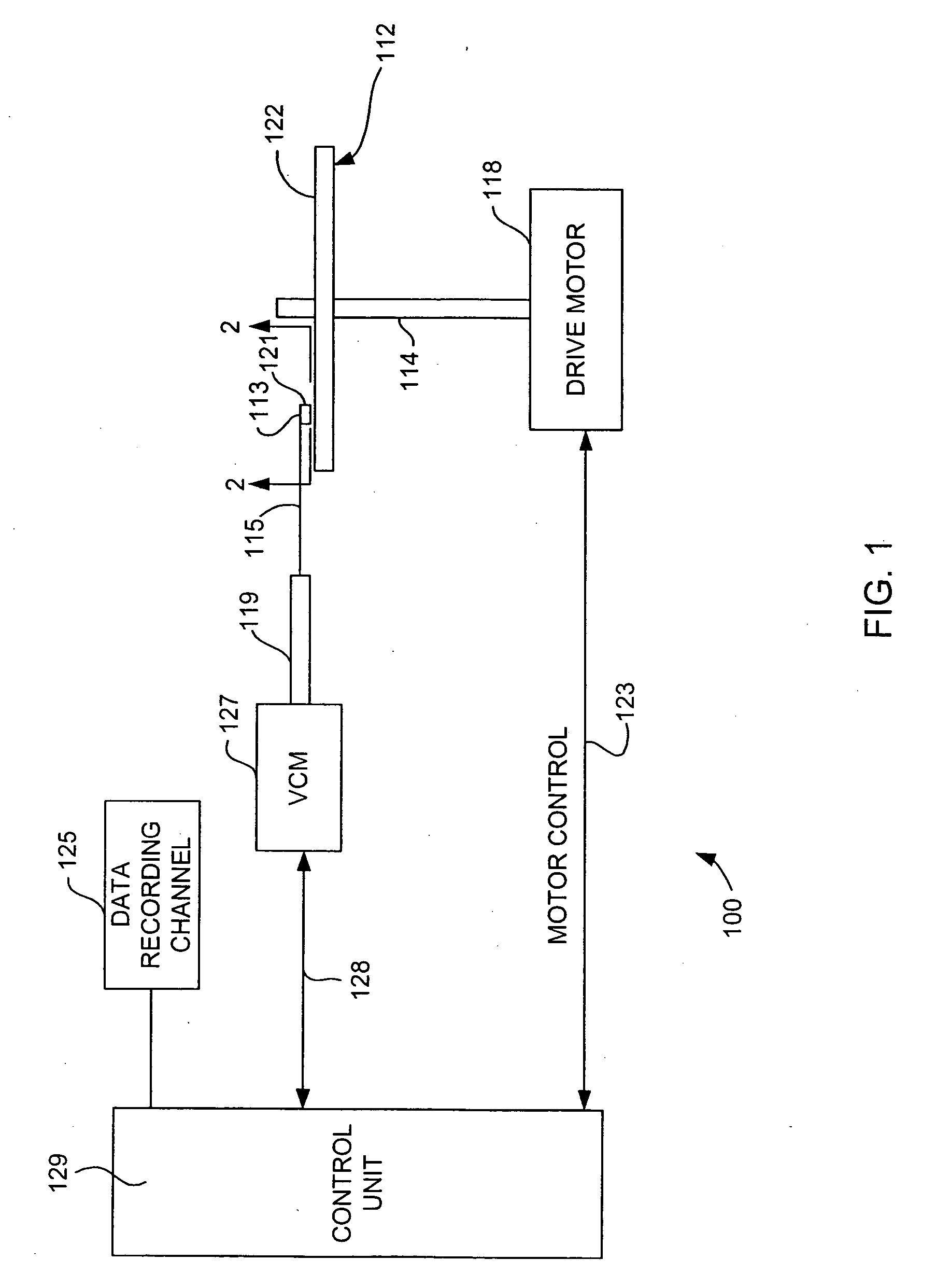
[0034] Referring now to FIG. 1, there is shown a disk drive 100 in which the present invention may be embodied. As shown in FIG. 1, at least one rotatable magnetic disk 112 is supported on a spindle 114 and rotated by a disk drive motor 118. The magnetic recording on each disk is in the form of annular patterns of concentric data tracks (not shown) on the magnetic disk 112.

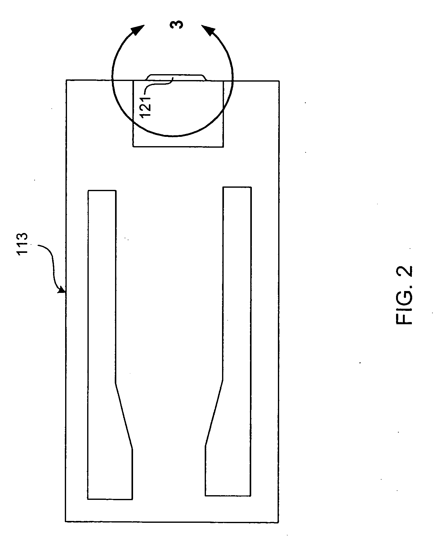
[0035] At least one slider 113 is positioned near the magnetic disk 112, each slider 113 supporting one or more magnetic head assemblies 121. As the magnetic disk rotates, slider 113 moves radially in and out over the disk surface 122 so that the magnetic head assembly 121 may access different tracks of the magnetic disk where desired data...


PUM

PropertyMeasurementUnit
electrically conductiveaaaaaaaaaa
widthaaaaaaaaaa
height distanceaaaaaaaaaa

Abstract

A magnetoresistive sensor having a lead overlay defined trackwidth and a pinned layer that extends beyond the stripe height defined by the free layer of the sensor. The extended pinned layer has a strong shape induced anisotropy that maintains pinning of the pinned layer moment. The extended portion of the pinned layer has sides beyond the stripe height that are perfectly aligned with the sides of the sensor within the stripe height. This perfect alignment is made possible by a manufacturing method that uses a mask structure for more than one manufacturing phase, eliminating the need for multiple mask alignments. The lead overlay design allows narrow, accurate trackwidth definition.

Description

FIELD OF THE INVENTION [0001] The present invention relates to magnetoresistive sensors and more particularly the construction of a magnetoresistive sensor having a pinned layer that is extended in the stripe height direction to increase shape induced magnetic anisotropy and thereby improve pinning, and that has a lead overlay structure for improved trackwidth control and sensor performance. BACKGROUND OF THE INVENTION [0002] The heart of a computer's long term memory is an assembly that is referred to as a magnetic disk drive. The magnetic disk drive includes a rotating magnetic disk, write and read heads that are suspended by a suspension arm adjacent to a surface of the rotating magnetic disk and an actuator that swings the suspension arm to place the read and write heads over selected circular tracks on the rotating disk. The read and write heads are directly located on a slider that has an air bearing surface (ABS). The suspension arm biases the slider into contact with the sur...

Claims


Application Information

Patent Timeline
Patent Type & Authority Applications(United States)
IPC IPC(8): G11B5/33G11B5/127
CPCB82Y25/00G01R33/093G11B5/3163G11B5/398G11B5/3906
Inventor FREITAG, JAMES MACHO, KUOK SANPINARBASI, MUSTAFA MICHAELTSANG, CHING HWA
Owner WESTERN DIGITAL TECH INC
Why Eureka
Try Eureka