Roller chain transmission device

a technology of transmission device and roller chain, which is applied in the direction of belt/chain/gearing, chain elements, chain elements, etc., can solve the problems of reducing the diameter of the pin, and reducing so as to reduce the strength of the chain, increase the diameter, and enhance the strength of the pin

Active Publication Date: 2006-07-18
TSUBAKIMOTO CHAIN CO
View PDF10 Cites 3 Cited by
  • Summary
  • Abstract
  • Description
  • Claims
  • Application Information

AI Technical Summary

Benefits of technology

[0013]When d / P is set to 0.40 or more, the strength of the pin is enhanced as a result of its increased diameter, so that snapping of the pin under the high loads encountered during high speed rotation is avoided. On the other hand, when d / P is more than 0.44, the walls of the bushing and the roller necessarily become too thin, and, as a result, the strength of the chain is undesirably reduced. Furthermore, it is necessary to maintain the wall thicknesses of the bushing and roller at conventional levels to maintain the shock resistance of the bushing and roller. Accordingly, D / P is set to a value within the range from 0.72 to 0.79 when d / P is set to a value within the range from 0.40 to 0.44.
[0014]Furthermore, when d / P conforms to the relation 0.40≦d / P≦0.44, the diameter of the bushing is greater than the diameter of a conventional bushing. Thus, the minimum cross-section of the inner link (that is a vertical cross-section taken through the axis of the bushing) is reduced. The reduction of the cross-section of the inner link would result in a reduction in strength. Accordingly, the reduction in the minimum cross-section is suppressed by increasing the height H of the inner link, which is about 86% of the chain pitch P in a conventional roller chain, to at least 96% of the chain pitch.
[0015]The sprocket used with the roller chain, has a tooth form calculated in accordance with the reference size calculation equation defined in ISO 606 (BS 228). However, the radius r of the arc of the tooth gap bottom satisfies the relation 0.505D≦r≦0.505D+0.069{square root over (D)}. This relationship ensures smooth movement of the sprocket at engagement and disengagement with the roller chain. When the radius of the arc of the tooth gap bottom deviates from this range, the efficiency of transmission of rotational torque from the chain to the sprocket is undesirably reduced.
[0016]In the roller chain transmission mechanism according to the invention, the outer diameter D of the roller and the outer diameter d of the pin satisfy the relations 0.72≦D / P≦0.79, and 0.40≦d / P≦0.44 with respect to the pitch P, and the height H of the inner plate satisfies the relation 0.96P≦H. Accordingly, the diameter of the pin is increased and pin rupture strength is remarkably enhanced so that the roller chain articulates smoothly over a long period of time.
[0017]Furthermore, since the diameter of the pin is increased, the contact area between the pin and the bushing is increased so that the contact stress on the pin and the bushing, is decreased. As a result, wear of the pin and the bushing is reduced, and elongation of the chain is suppressed, so that proper engagement of the chain with the sprocket is realized over a long period of time. Further, since the minimum cross-section of the inner link is increased, stress concentration at the location where the bushing is press fit into the inner can be avoided.
[0018]Since the sprocket satisfies the relation 0.505D≦r≦0.505D+0.069{square root over (D)}, the radius r of the arc of the tooth gap bottom is also increased and larger than the corresponding radius in a conventional sprocket. As a result, the contact surface pressure between the roller and the sprocket becomes smaller than in the conventional case, so that wear in the sprocket teeth under high load is suppressed.

Problems solved by technology

These standards have generally been adhered to because it has been considered that, when the ratio D / P is too high, the widths of the sprocket teeth become excessively small and insufficiently strong.
On the other hand, when the ratio D / P is too low, the outer diameter d of the pins, which extend through the bushings, is decreased, which leads to reduction in the strength of the chain.
It has been reported that, when the above-mentioned conventional roller chains were used as timing chains in an automobile engine under high loads, for example 4 kN, some of the chains failed to exhibit the expected durability.
As a result of intensive study of the above problems, we have found that the “elongation—wear Resistance” of a roller chain, which may be within the allowable range in other applications, becomes critical when a roller chain is used as a camshaft drive chain for precision timing in an automobile engine, and unexpectedly high loads are applied to the chain link connected pins at higher engine speeds.
Furthermore, it has become clear that the specified standard tooth forms of conventional sprockets are not necessarily optimum from the standpoint of wear resistance.

Method used


Image

  • Roller chain transmission device
  • Roller chain transmission device
  • Roller chain transmission device

Examples


Embodiment Construction

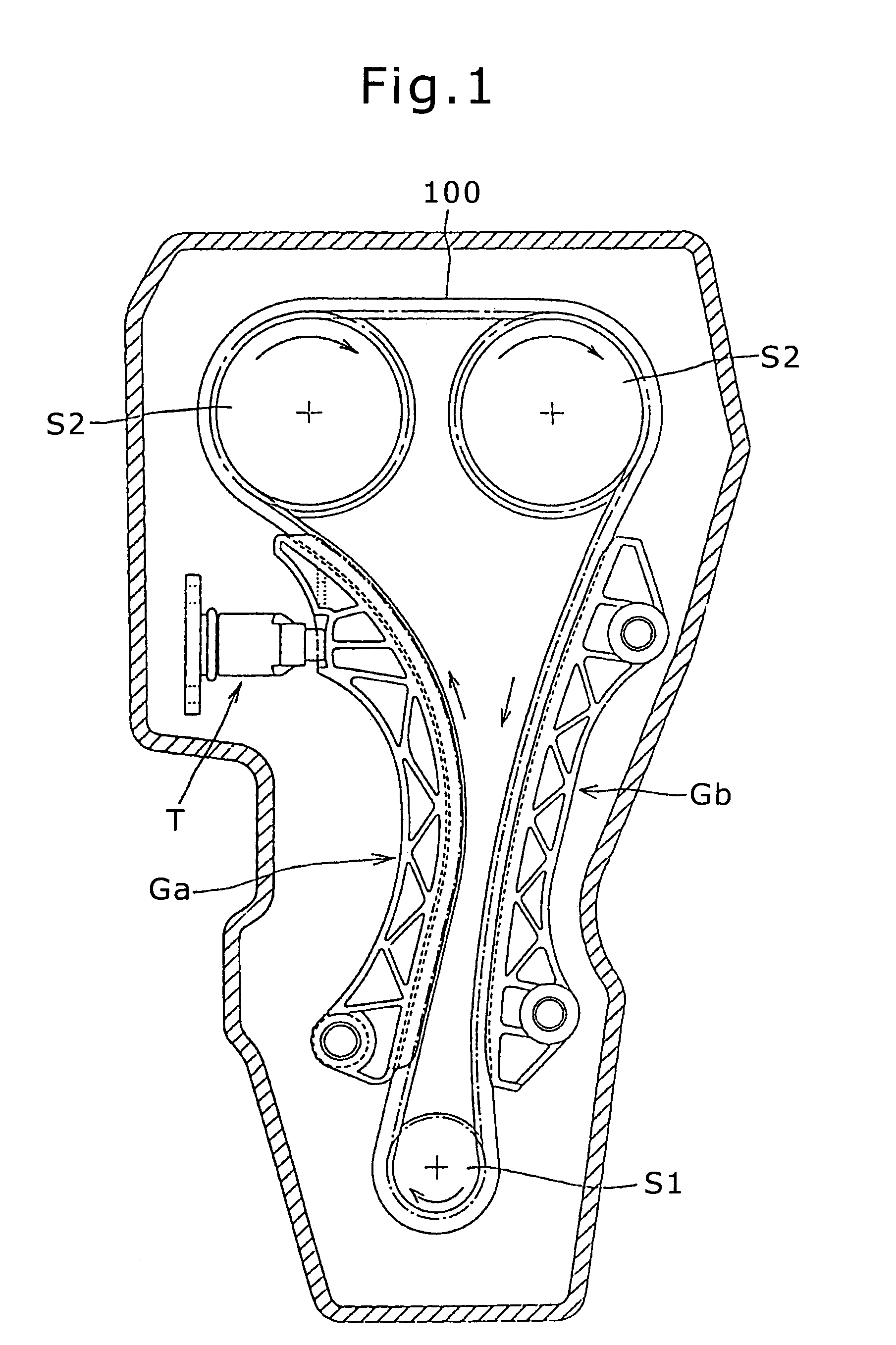
[0026]In the transmission shown in FIG. 1 a roller chain 100 is in mesh with a driving sprocket S1 on a crankshaft (not shown) and a pair of driven camshaft sprockets S2. A movable guide Ga cooperating with a tensioner T is in sliding contact with the chain 100 and imparts tension to the chain. A fixed guide Gb regulates the traveling path of the chain 100.

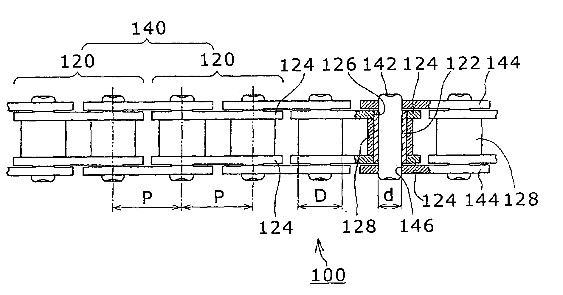
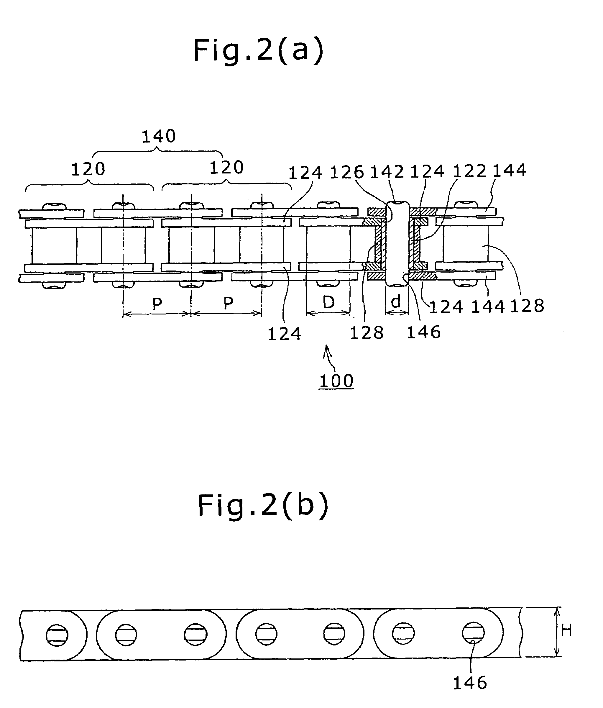
[0027]As shown in FIGS. 2(a) and 2(b), the roller chain 100 comprises inner links 120 having cylindrical bushings 122, and inner plates 124, with bushing holes 126, in which the opposite ends the bushings 122 are secured. Rollers 128 are rotatable on the bushings 122. Outer links 140 are composed of outer plates 144 and pins 142. The outer plates 144 are disposed on the outsides of the pairs of inner plates 124 in overlapping relationship. The pins 142 extend rotatably through the bushings, and have both ends secured in pin holes 146 in the outer plates 144.

[0028]The sizes of the respective elements are selected so that the outer ...


PUM


Abstract

In a roller chain transmission, the diameter D of the rollers, the outer diameter d of the pins, and the height H of the inner plates satisfy the relationships 0.72P≦D≦0.79P, 0.40P≦d≦0.44P, and 0.96P≦H, with respect to the chain pitch P. The radius r of the arc of the tooth gap bottom of the sprocket teeth satisfies the relationship 0.505D≦r≦0.505D+0.069{square root over (D)}. The transmission chain exhibits high durability due to improved strength and wear resistance under high loads.

Description

FIELD OF THE INVENTION[0001]This invention relates to a roller chain transmission of the kind used for power transmission in an automobile, an industrial machine, or a conveyor. The invention has particular utility as a timing transmission in an automobile engine, for driving a valve-operating camshaft.BACKGROUND OF THE INVENTION[0002]In recent years, roller chains have come into increasing use, as a result of the demand for high load capacity, high speed operation and maintenance-free operation. For these reasons, roller chains have displaced toothed belts, which were previously commonly used in automotive timing drives.[0003]As shown in FIGS. 7(a)–7(c), a conventional roller chain 500 for a timing transmission comprises an inner link 520 (FIG. 7(b)) and an outer link 540 (FIG. 7(c). In the inner link 520, both ends of each of two cylindrical bushings 522 fit into bushing holes 526 in a pair of inner plates 524, and rollers 528 are rotatable on the bushings 522. In the outer link 5...

Claims


Application Information

Patent Timeline
Patent Type & Authority Patents(United States)
IPC IPC(8): F16G13/06F16H7/06
CPCF16G13/06
Inventor OKABE, ISAMUKOGA, TOMOTAKA
Owner TSUBAKIMOTO CHAIN CO
Why Eureka
Try Eureka