Compact load path swashplate assembly
- Summary
- Abstract
- Description
- Claims
- Application Information
AI Technical Summary
Benefits of technology
Problems solved by technology
Method used
Image
Examples
Embodiment Construction
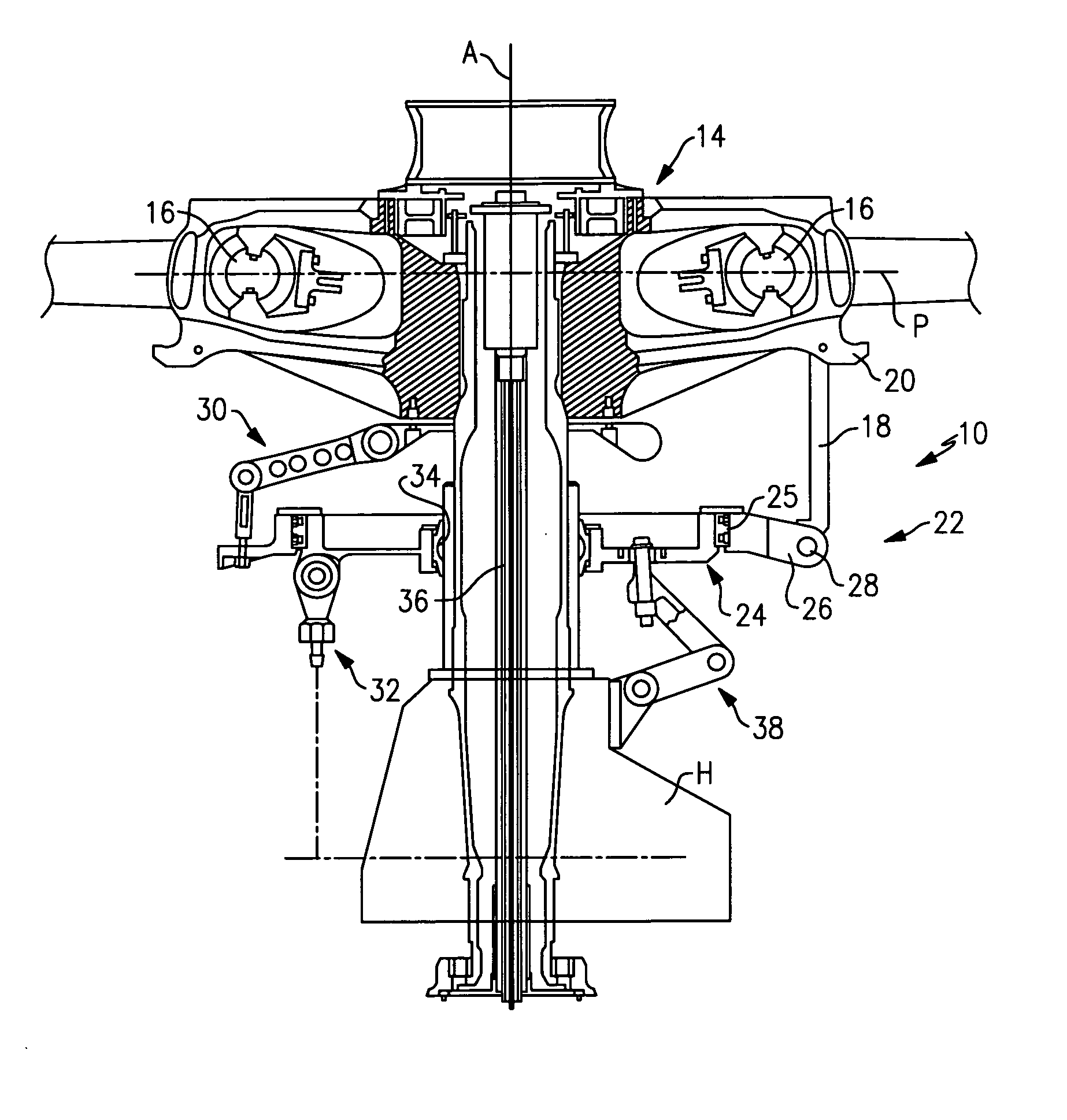
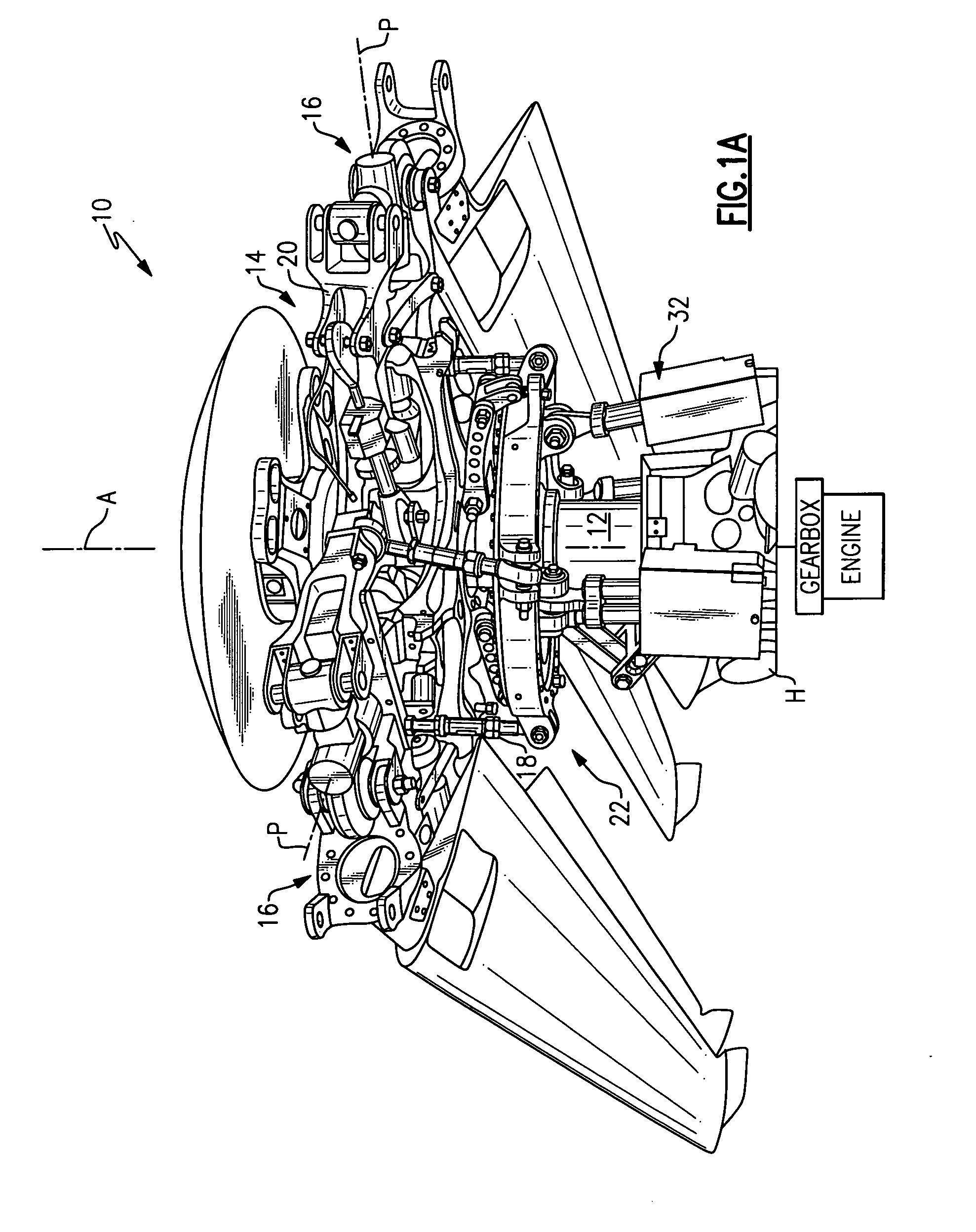
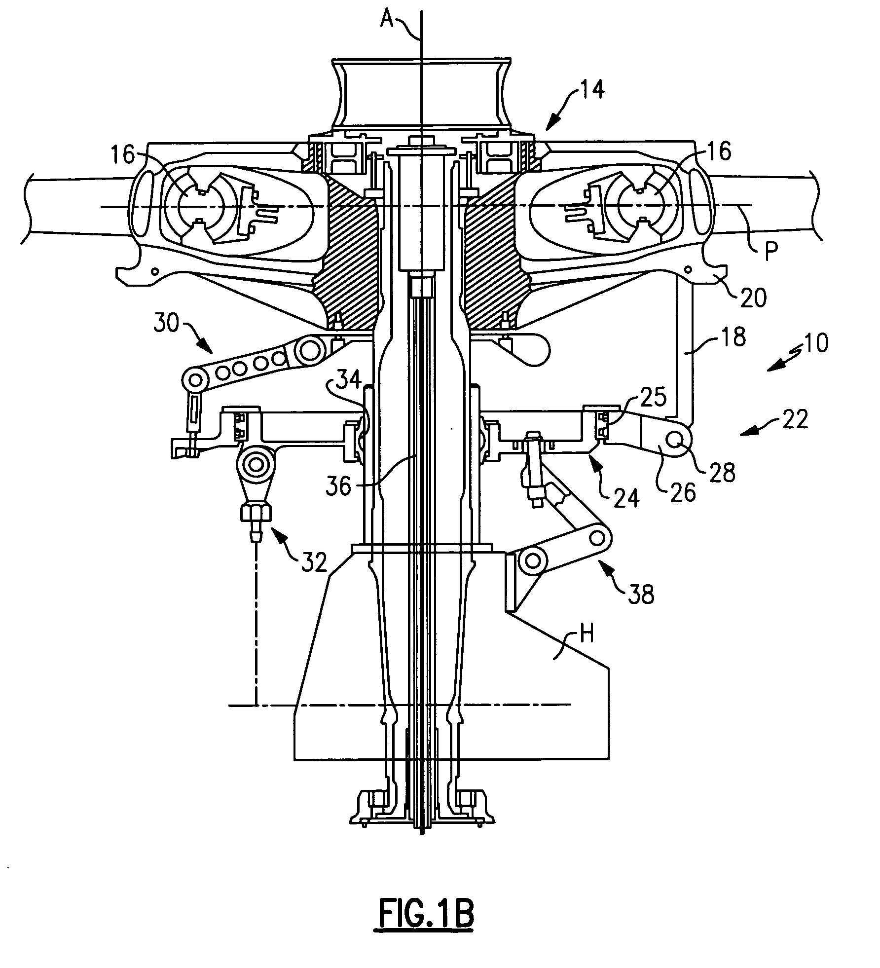
[0023]FIG. 1A illustrates a general perspective view of a rotor system 10 which includes a rotor shaft 12 driven in conventional fashion by an engine through a reduction gearing for rotation about an axis of rotation A. A rotor hub 14 is mounted to the rotor shaft 12 for rotation therewith about an axis of rotation to support a multiple of rotor blade assemblies 16 (illustrated schematically) therefrom.
[0024] Each blade assembly 16 is mounted to the rotor hub 14 so as to be flexible about a pitch change axis P (blade assemblies shown folded in FIG. 1A). It should be understood that various attachment systems and rotor blade pitch change systems are usable with the present invention. Pitch change loads are imparted to each rotor blade assembly 16 by pitch control rods 18 which are articulatably connected at one end to the rotor blade assembly 16 at a pitch horn 20. The opposite end of the pitch control rod 18 is articulately connected to a swash plate assembly 22.
[0025] Referring t...
PUM
 Abstract
Description
Claims
Application Information
 - R&D
- Intellectual Property
- Life Sciences
- Materials
- Tech Scout
- Unparalleled Data Quality
- Higher Quality Content
- 60% Fewer Hallucinations
Browse by: Latest US Patents, China's latest patents, Technical Efficacy Thesaurus, Application Domain, Technology Topic, Popular Technical Reports.
© 2025 PatSnap. All rights reserved.Legal|Privacy policy|Modern Slavery Act Transparency Statement|Sitemap|About US| Contact US: help@patsnap.com


