Compact load path swashplate assembly

a swash plate and load path technology, applied in the field of rotary wing aircraft, can solve the problems of uncomplicated and lightweight arrangemen

Active Publication Date: 2012-03-27
SIKORSKY AIRCRAFT CORP
View PDF37 Cites 19 Cited by
  • Summary
  • Abstract
  • Description
  • Claims
  • Application Information

AI Technical Summary

Benefits of technology

[0009]A swash plate assembly according to the present invention includes a rotationally stationary swash plate and rotational swash plate which rotates relative to the rotationally stationary swash plate through a bearing system. The bearing system includes a duplex bearing which need not increase to accommodate bolt or expandable pin removal as typical of conventional systems. Such a bearing system provides for an uncomplicated and lightweight arrangement.
[0010]Each servo control rod is attached to the swash plate assembly to communicate control inputs thereto through a respective servo lug. Each servo lug defines a servo pivot point off an in-line plane inboard of the bearing system. As the servo lugs extend below the rotationally stationary swash plate, a relatively uncomplicated attachment arrangement is facilitated as compared to a more conventional trunion attachment. Attachment is provided by a servo lug fastener such as bolted connection. Such attachment facilitates for redundant locking features at a highly inspectable location which simplifies maintenance and increases safety.
[0013]The present invention therefore provides an uncomplicated, short load path swash plate assembly which provides the desired compactness.

Problems solved by technology

Such a bearing system provides for an uncomplicated and lightweight arrangement.

Method used


Image

  • Compact load path swashplate assembly
  • Compact load path swashplate assembly
  • Compact load path swashplate assembly

Examples


Embodiment Construction

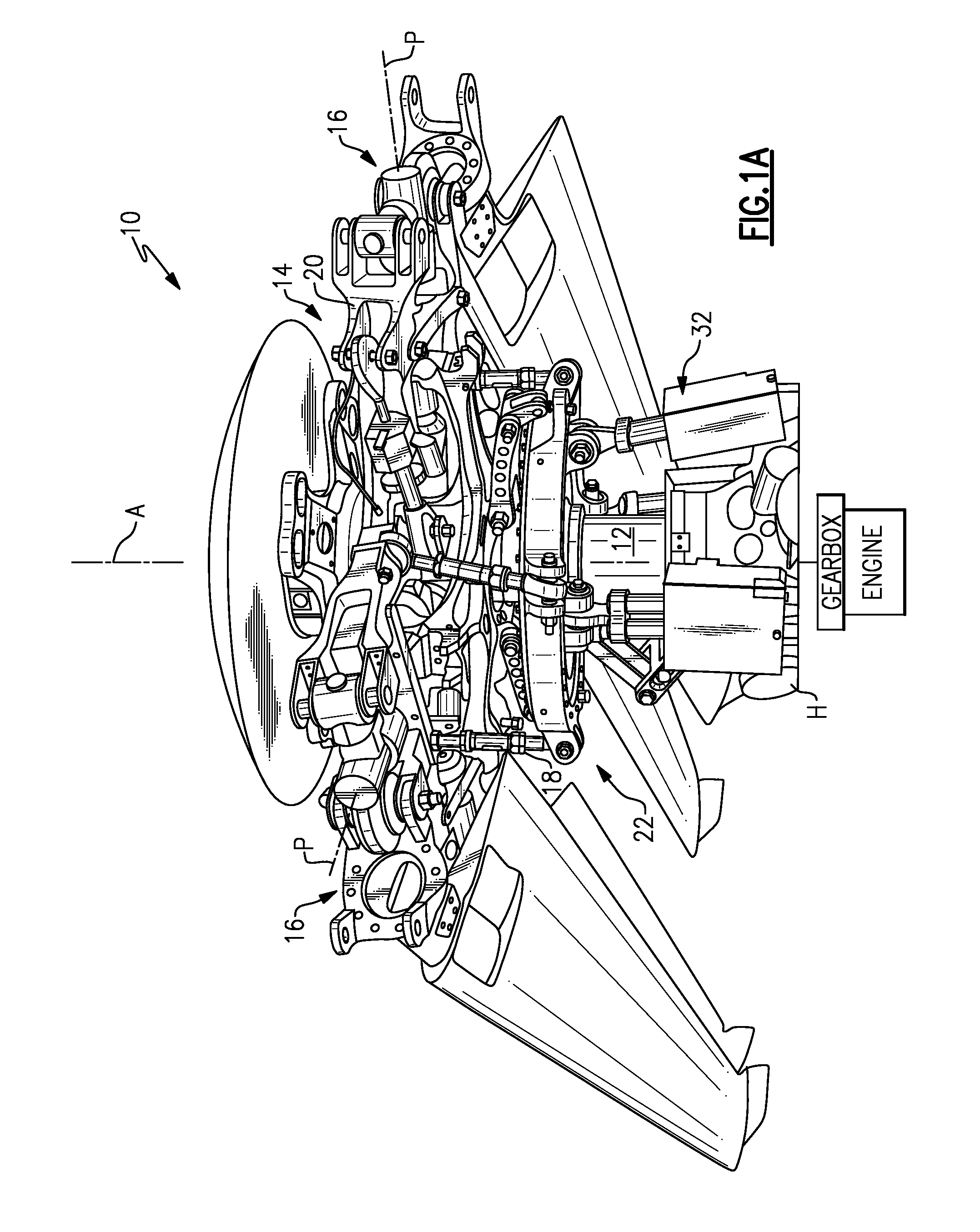
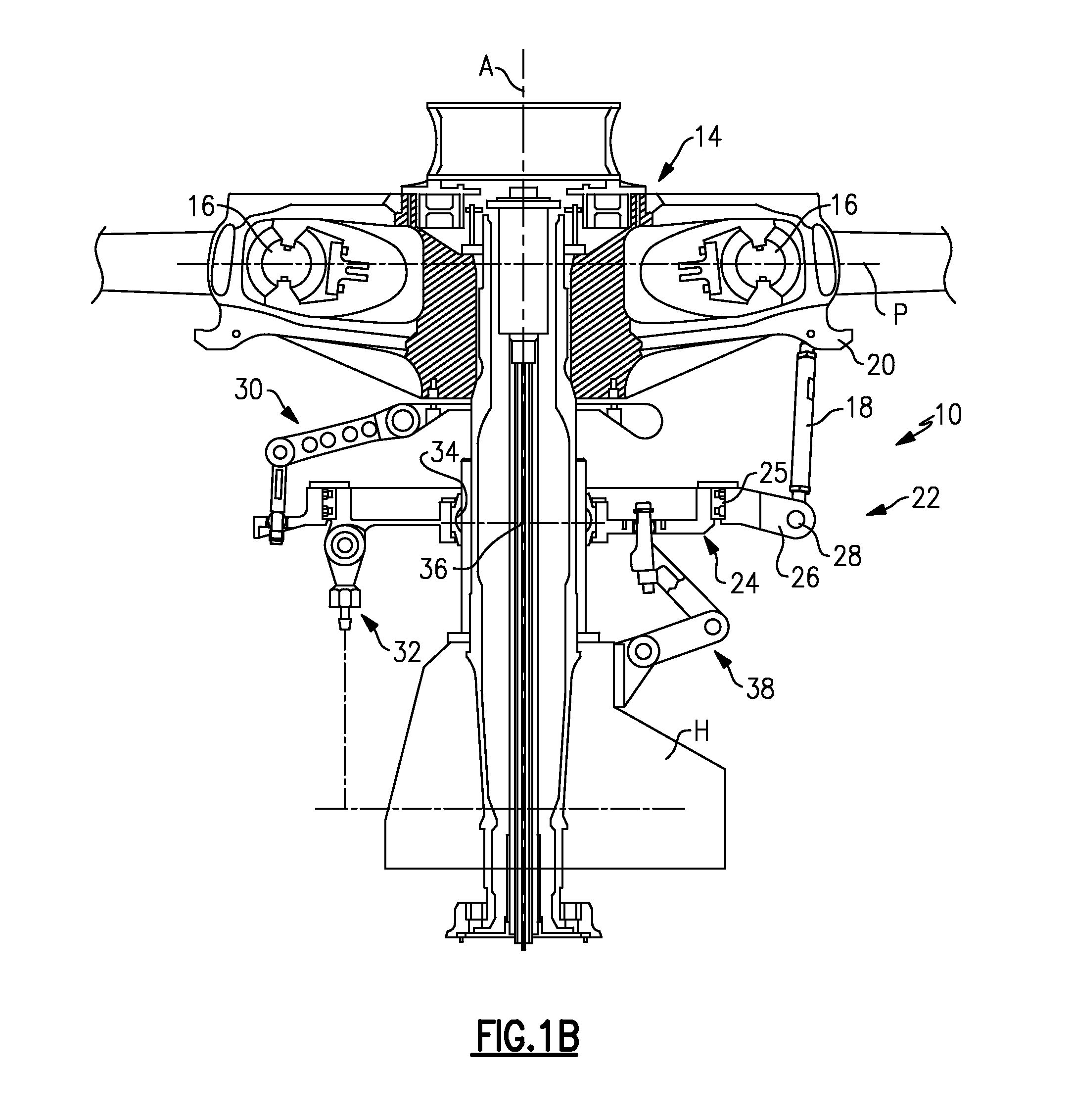
[0023]FIG. 1A illustrates a general perspective view of a rotor system 10 which includes a rotor shaft 12 driven in conventional fashion by an engine through a reduction gearing for rotation about an axis of rotation A. A rotor hub 14 is mounted to the rotor shaft 12 for rotation therewith about an axis of rotation to support a multiple of rotor blade assemblies 16 (illustrated schematically) therefrom.

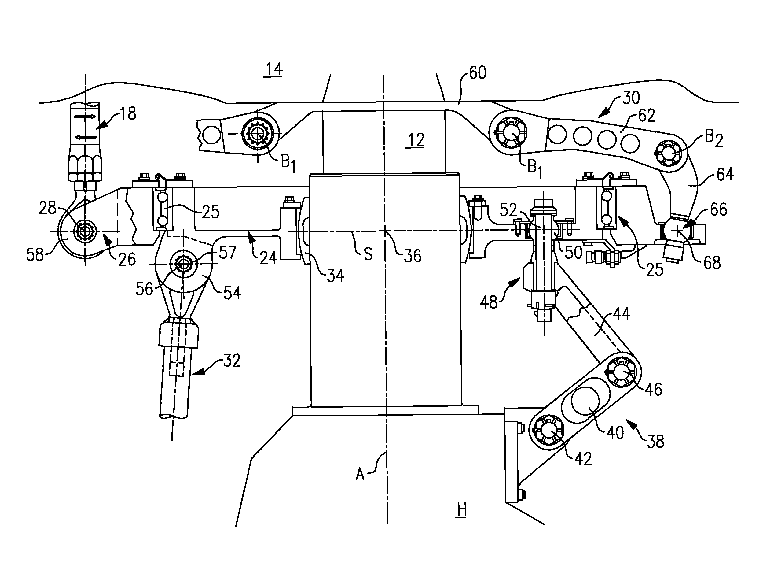
[0024]Each blade assembly 16 is mounted to the rotor hub 14 so as to be flexible about a pitch change axis P (blade assemblies shown folded in FIG. 1A). It should be understood that various attachment systems and rotor blade pitch change systems are usable with the present invention. Pitch change loads are imparted to each rotor blade assembly 16 by pitch control rods 18 which are articulatably connected at one end to the rotor blade assembly 16 at a pitch horn 20. The opposite end of the pitch control rod 18 is articulately connected to a swash plate assembly 22.

[0025]Referring to FI...


PUM


Abstract

A swash plate assembly includes a rotationally stationary swash plate and rotational swash plate which rotates relative to the rotationally stationary swash plate through a bearing system. Each servo control rod is attached to the swash plate assembly to communicate control inputs thereto through a respective servo lug. Each servo lug defines a servo pivot point off an in-line plane inboard of the bearing system. As the servo lugs extend below the rotationally stationary swash plate, a relatively uncomplicated attachment arrangement is facilitated which provides for redundant locking features at a highly inspectable location which simplifies maintenance and increased safety. By locating the servo pivot point just inboard of the bearing system, an exceeding compact load path is defined thereby. The load path is defined from the servo control, to the servo lug, through the rotationally stationary swash plate, bearing system, the rotational swash plate, the rotor pitch control point and into the pitch control rod.

Description

BACKGROUND OF THE INVENTION[0001]The present invention relates to a rotary wing aircraft, and more particularly to an in-line swash plate assembly for controlling the main rotor blade pitch of a rotary wing aircraft main rotor system.[0002]Control of a helicopter is affected by varying the pitch of the rotor blades individually as the rotor rotates and by varying the pitch of all of the blades together. These are known respectively as cyclic and collective pitch control. Blade pitch control of a rotary wing aircraft main rotor is typically achieved through a swash plate assembly which transfers the motion of non-rotating control members to the rotating members.[0003]The swash plate assembly is typically concentrically mounted about a rotor shaft. The swash plate assembly generally includes two rings connected by a series of bearings with one ring connected to the airframe (stationary), and the other ring connected to the rotor hub (rotating). The rotating ring is connected to the ro...

Claims


Application Information

Patent Timeline
Patent Type & Authority Patents(United States)
IPC IPC(8): B64C27/04
CPCB64C27/605
Inventor SCHMALING, DAVID N.ROBBINS, MICHAEL R.D'ANNA, FRANK P.
Owner SIKORSKY AIRCRAFT CORP
Why Eureka
Try Eureka