System-On-a-Chip mixed bus architecture

a mixed bus and system technology, applied in the field of system on chip architectures, can solve the problem of limited resource communication of the second dma controller, and achieve the effect of mitigating bus errors

Inactive Publication Date: 2007-06-07
IBM CORP
View PDF3 Cites 23 Cited by
  • Summary
  • Abstract
  • Description
  • Claims
  • Application Information

AI Technical Summary

Benefits of technology

[0010] This invention comprises a method and system that mitigates bus error in a mixed system on chip architecture.

Problems solved by technology

Communication of the second DMA controller is limited to resource of the AMBA system on-chip architecture.

Method used


Image

  • System-On-a-Chip mixed bus architecture
  • System-On-a-Chip mixed bus architecture
  • System-On-a-Chip mixed bus architecture

Examples


Embodiment Construction

Overview

[0018] A CoreConnect system on chip architecture is mixed with an AMBA system on chip architecture. The mixed architecture includes a circuit with an additional on-chip peripheral bus and two additional bridges. The addition of the circuit to the mixed architecture removes a bus error that sometimes occurs with the transfer of data between the processor local bus and an advanced high performance bus of the AMBA SoC architecture.

Technical Details

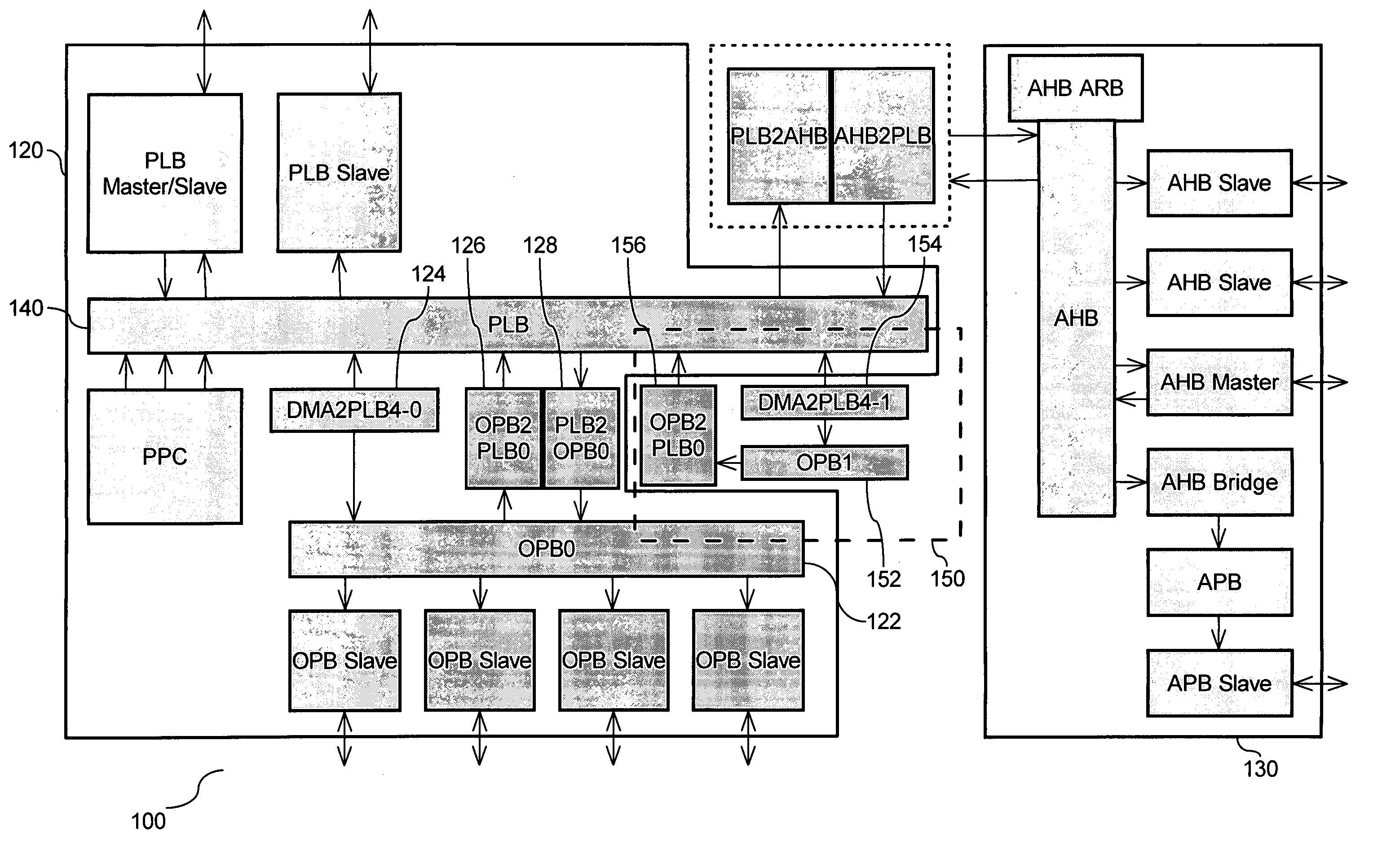
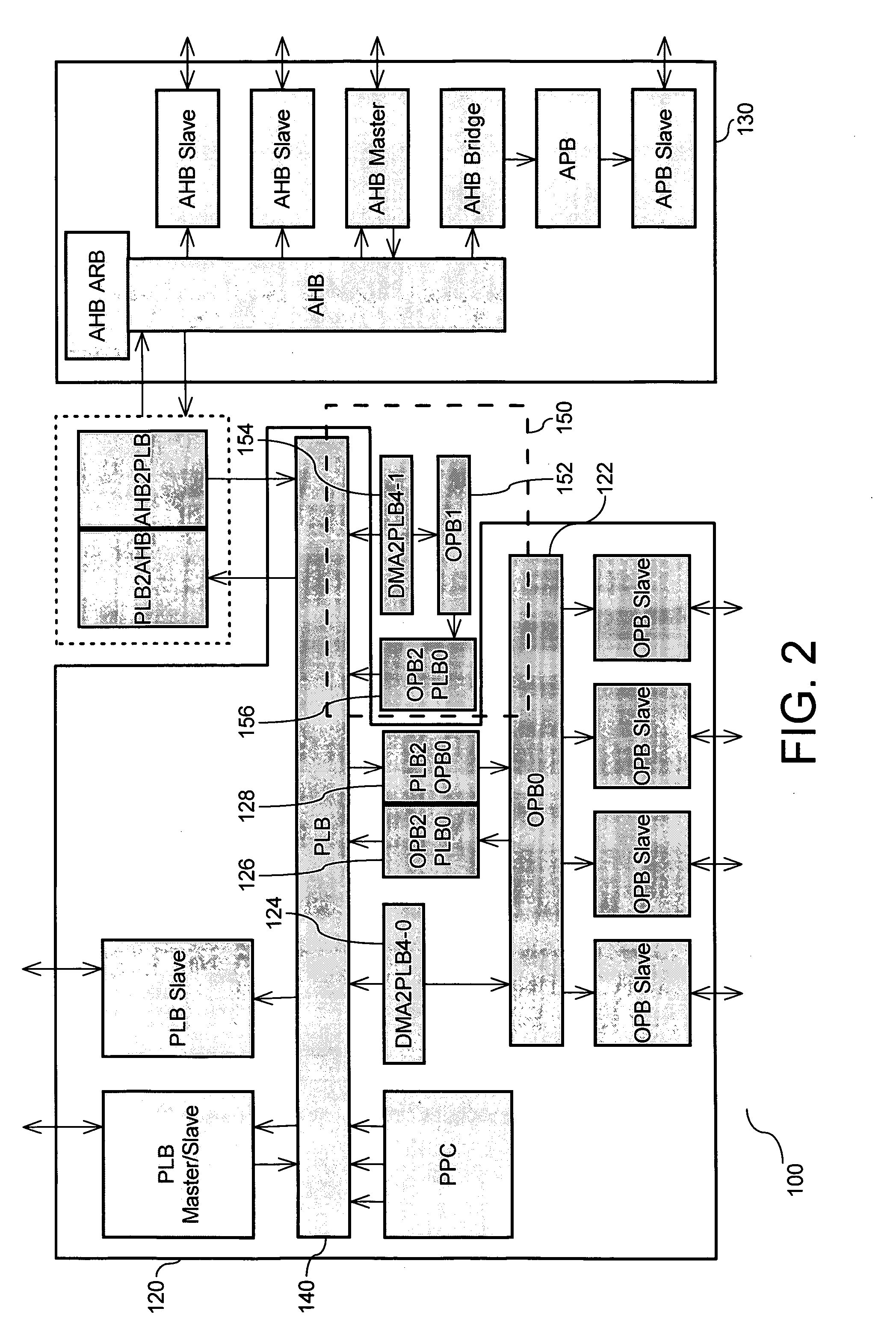
[0019]FIG. 2 is a schematic diagram (100) of a bus architecture mixing the CoreConnect architecture (120) with the AMBA architecture (130) and showing a solution to the bus error. As shown, a circuit (150) is provided joining the two architectures. The circuit (150) includes an additional OPB bus (152) to the CoreConnect OPB bus (122). For reference purposes only, the CoreConnect OPB Bus (122) is referred to as a first OPB Bus, and it resides external to the circuit (150). The additional OPB Bus (152) is referred to as a second OPB...


PUM


Abstract

A mixed architecture system on chip is provided by combining a CoreConnect system on chip architecture with an AMBA system on chip architecture. To eliminate data transfer and bus error that could occur in the mixed architecture, an additional peripheral bus and bridge are provided to manage communication with AHB resources.

Description

BACKGROUND OF THE INVENTION [0001] 1. Technical Field [0002] This invention relates to system on chip architectures. More specifically, this invention relates to combining the CoreConnect architecture with the AMBA architecture. [0003] 2. Description of the Prior Art [0004] Core Connect bus architecture owned by IBM is a standard System-On-a-Chip (SoC) design that allows peripherals formerly attached to the processor at the card level to be integrated onto the same die as the processor. The Core Connect architecture provides the following three buses for interconnecting core, library macros, and custom logic: processor local bus (PLB), on-chip peripheral bus (OPB), and device control register (DCR). The PLB and OPB buses provide the primary means for data flow among macro elements. The PLB generally interconnects high-bandwidth devices, such as processor cores, external memory interfaces, and DMA controllers. The PLB addresses the high performance, low latency and design flexibility...

Claims


Application Information

Patent Timeline
Patent Type & Authority Applications(United States)
IPC IPC(8): G06F13/36
CPCG06F13/28G06F13/4027
Inventor MATSUSE, SHUHSAKUUEDA, MAKOTO
Owner IBM CORP
Why Eureka
Try Eureka