
System and method for regenerating a diesel particulate filter

a technology of particulate filter and system, which is applied in the direction of engine components, machines/engines, mechanical equipment, etc., can solve the problems of ineffective doc-dpf assembly, reduced engine efficiency, and inability to increase engine speed

Inactive Publication Date: 2007-06-14
HYUNDAI MOTOR CO LTD
View PDF6 Cites 9 Cited by
  • Summary
  • Abstract
  • Description
  • Claims
  • Application Information

AI Technical Summary

Benefits of technology

The present invention provides a system and method for regenerating a diesel particulate filter. The system includes a fixing part for fixing a housing of a diesel oxidation catalyst-diesel particulate filter assembly, a fluid supplying part for supplying a fluid of high temperature and high pressure to the rear end of the housing, a fluid intake part for taking in the fluid, and a controller for controlling the fluid supplying part such that the temperature of the fluid between the diesel oxidation catalyst and the diesel particulate filter reaches a first predetermined temperature. The system also includes a first plug for opening and closing a pre-existing inlet at the front end of the housing and a second plug for opening and closing the second outlet. The method includes removing the assembly from the exhaust system, fixing the assembly, connecting pipes, operating the pump, turbine, and burner, determining whether the temperature reaches a predetermined level, and stopping the pump, turbine, and burner until the temperature reaches the predetermined level. The technical effects of the invention include enabling reuse of the diesel particulate filter and reducing emissions from diesel engines.

Problems solved by technology

In addition, if the PM is excessively deposited on the diesel particulate filter, engine efficiency may be reduced since the exhaust system does not operate at full performance.
However, if the PM is excessively deposited on the diesel particulate filter, the engine speed may not be increased since the exhaust backpressure is excessively increased.
As a result, since the PM is not burned, the expensive DOC-DPF assembly becomes ineffectual so it must be replaced.

Method used


Image

  • System and method for regenerating a diesel particulate filter
  • System and method for regenerating a diesel particulate filter
  • System and method for regenerating a diesel particulate filter

Examples


Embodiment Construction

[0025] With reference to the accompanying drawings, the present invention will be described in order for those skilled in the art to be able to implement the invention. As those skilled in the art would realize, the described embodiments may be modified in various different ways, all without departing from the spirit or scope of the present invention.

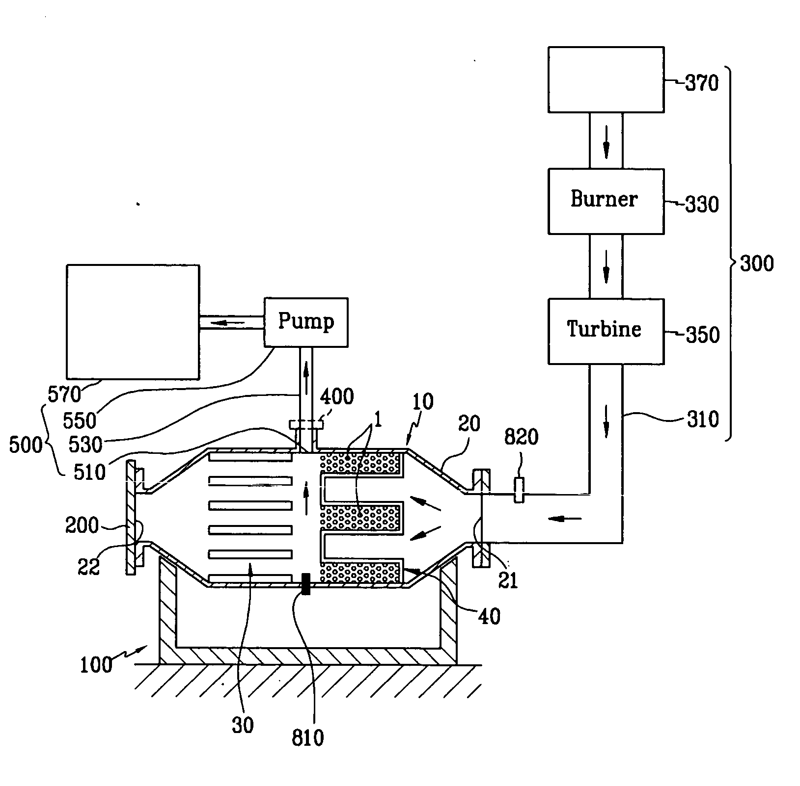
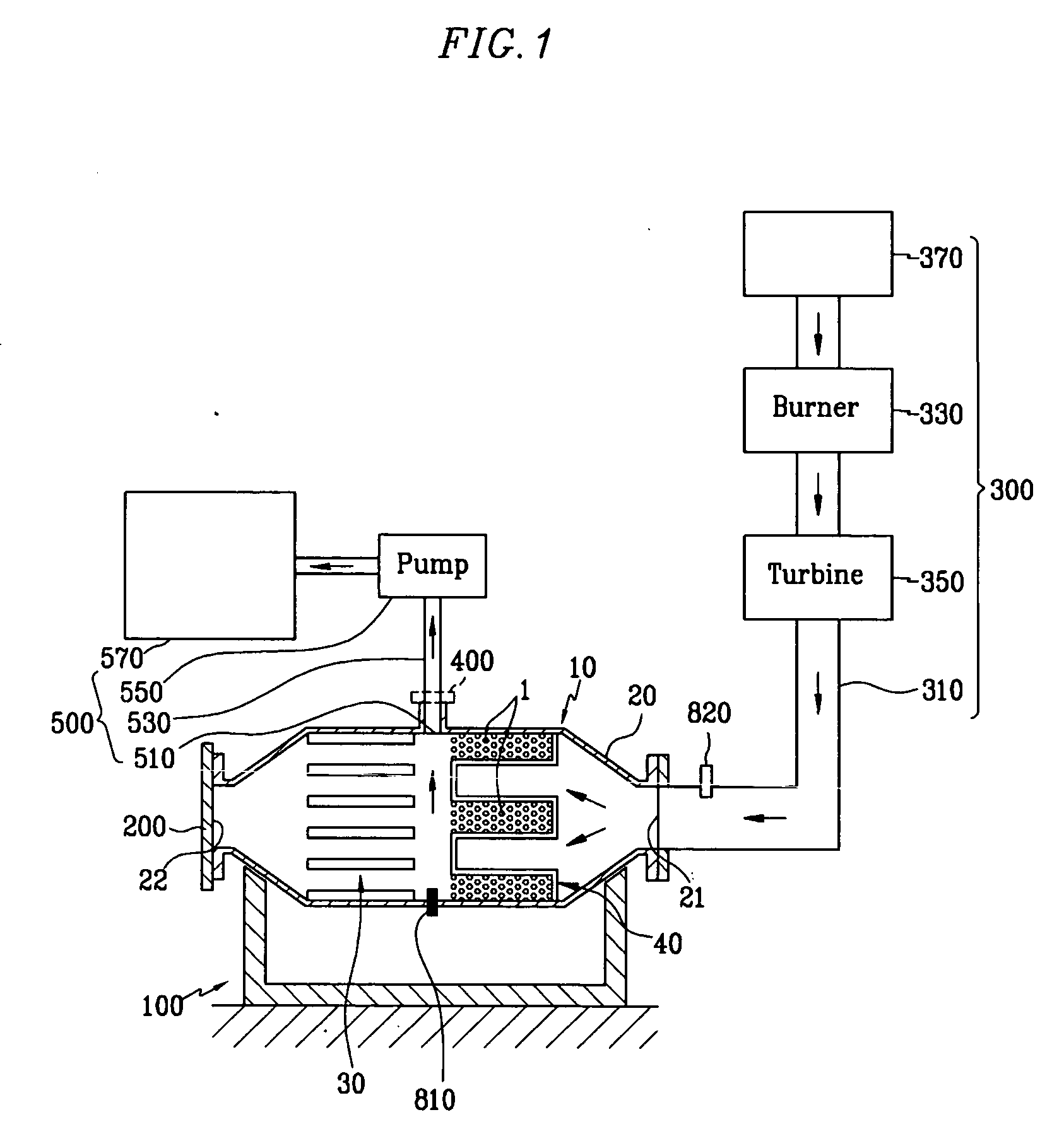
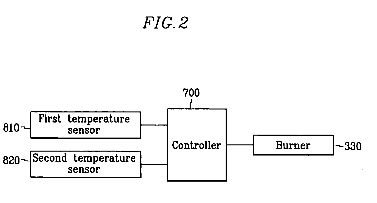
[0026]FIG. 1 is a schematic view showing a system for regenerating a diesel particulate filter according to an exemplary embodiment of the present invention. FIG. 2 is block diagram showing a controller and elements connected to the controller, in a system for regenerating a diesel particulate filter according to an exemplary embodiment of the present invention.

[0027] A system for regenerating a diesel particulate filter according to an exemplary embodiment of the present invention, as shown in FIGS. 1 and 2, includes a fixing part 100, a fluid supplying part 300, a fluid intake part 500, and a controller 700.

[0028] The fixing part 1...


PUM


Abstract

A system for regenerating a diesel particulate filter of the present invention includes a fixing part, a fluid supplying part, a fluid inhaling part, and a controller. The fixing part fixes a housing of a diesel oxidation catalyst-diesel particulate filter assembly. The fluid supplying part supplies a fluid of high temperature and high pressure to a rear end of the housing. The fluid inhaling part inhales the fluid from a space between the diesel oxidation catalyst and the diesel particulate filter of the housing. The controller controls the fluid supplying part such that temperature of the fluid between the diesel oxidation catalyst and the diesel particulate filter arrives at a first predetermined temperature.

Description

CROSS-REFERENCE TO RELATED APPLICATION [0001] This application claims priority to and the benefit of Korean Patent Application No. 10-2005-0122774 filed in the Korean Intellectual Property Office on Dec. 13, 2005, the entire contents of which are incorporated herein by reference. BACKGROUND OF THE INVENTION [0002] (a) Field of the Invention [0003] The present invention relates to a diesel oxidation catalyst (DOC)-diesel particulate filter (DPF) assembly, and in particular, to a system and a method for generating a diesel particulate filter. [0004] (b) Description of the Related Art [0005] In general, a DOC-DPF assembly includes a housing, a diesel oxidation catalyst, and a diesel particulate filter, and the diesel oxidation catalyst and the diesel particulate filter are sequentially mounted in the housing with respect to an exhaust direction. Such a DOC-DPF assembly is mounted in an exhaust system of a diesel engine so as to remove air pollution material exhausting from the diesel e...

Claims


Application Information

Patent Timeline
Patent Type & Authority Applications(United States)
IPC IPC(8): F01N3/00F01N3/10
CPCF01N3/0233F01N3/0237F01N3/025F01N3/02F01N3/023
Inventor SEO, JUNG MIN
Owner HYUNDAI MOTOR CO LTD
Learn More