
Internal turbine-like toroidal combustion engine

a combustion engine and turbine-like technology, applied in the direction of machines/engines, efficient propulsion technologies, mechanical apparatuses, etc., can solve the problems of engine evolution, engine but were dangerous and inefficient, and added to the complexity of the engin

Active Publication Date: 2007-06-14
MIRABILE NICHOLAS F
View PDF26 Cites 9 Cited by
  • Summary
  • Abstract
  • Description
  • Claims
  • Application Information

AI Technical Summary

Benefits of technology

[0013] According to the present invention, a novel combustion engine with turbine like properties is disclosed. The novel engine comprises an air intake, a first compressor stage, coupled to the air intake, a second compressor stage, coupled to the first compressor stage, a transfer valve, placed between the compressor stages and an annular race. Within the annular race, a turbine or toroidal piston travels and passes over the transfer valve. The valve, toroidal piston and race form a temporary combustion chamber that expands as the piston travels in its circular path within the annular race. Compressed air and fuel are introduced into the temporary combustion chamber and ignited to release the chemical energy and force the turbine piston to travel faster within the annular race. The first compressor stage is rotatably coupled to a crank shaft, which drives the first compressor stage. An armature connects the turbine piston to the drive shaft so that the movement of the piston will move the armature. The armature is further connected to the drive shaft so that useful work can be extracted from the energy released from the combustion of the fuel-air mixture.

Problems solved by technology

The evolution of engines began with steam engines, which were an external combustion engine, but were dangerous and inefficient.
A four stroke engine, by contrast, uses oil for lubricating the crank shaft and pistons and managing the oil flow could be troublesome and add to the complexity of the engine to solve this problem.
Unfortunately, two stroke gasoline engines have several problems as compared to a four stroke gasoline engine.
One is that the compression of the air-fuel mixture causes leaking past the cylinder out the exhaust port during each cycle.
This leaking is an environmental hazard.
Further, two stroke engines do not last as long as a four stroke engine.
The lack of a dedicated lubrication system means that the parts of a two stroke engine wear a lot faster than those in a four stroke engine.
Further, two stroke engine oil, mixed with the fuel to provide lubrication, is expensive and is consumed at a rate of about one gallon for every 1,000 miles if used as a car engine.
Lastly, two stroke engines are less efficient than four stroke engines, so fuel economy would suffer.
This design lends itself to large engine applications and is not practical for small engine applications, such as for applications of a gasoline two-stroke or four stroke engine.
The four stroke engine can be very efficient, but it loses power as compared to a two stroke engine since twice as many steps must be performed, meaning that only one combustion for every two revolutions can occur.
The main disadvantage of gas turbines is that, compared to a reciprocating engine of the same size, they are expensive.
They spin at such high speeds and such high temperatures that designing and manufacturing gas turbines is very difficult from an engineering and materials perspective.

Method used


Image

  • Internal turbine-like toroidal combustion engine
  • Internal turbine-like toroidal combustion engine
  • Internal turbine-like toroidal combustion engine

Examples


Embodiment Construction

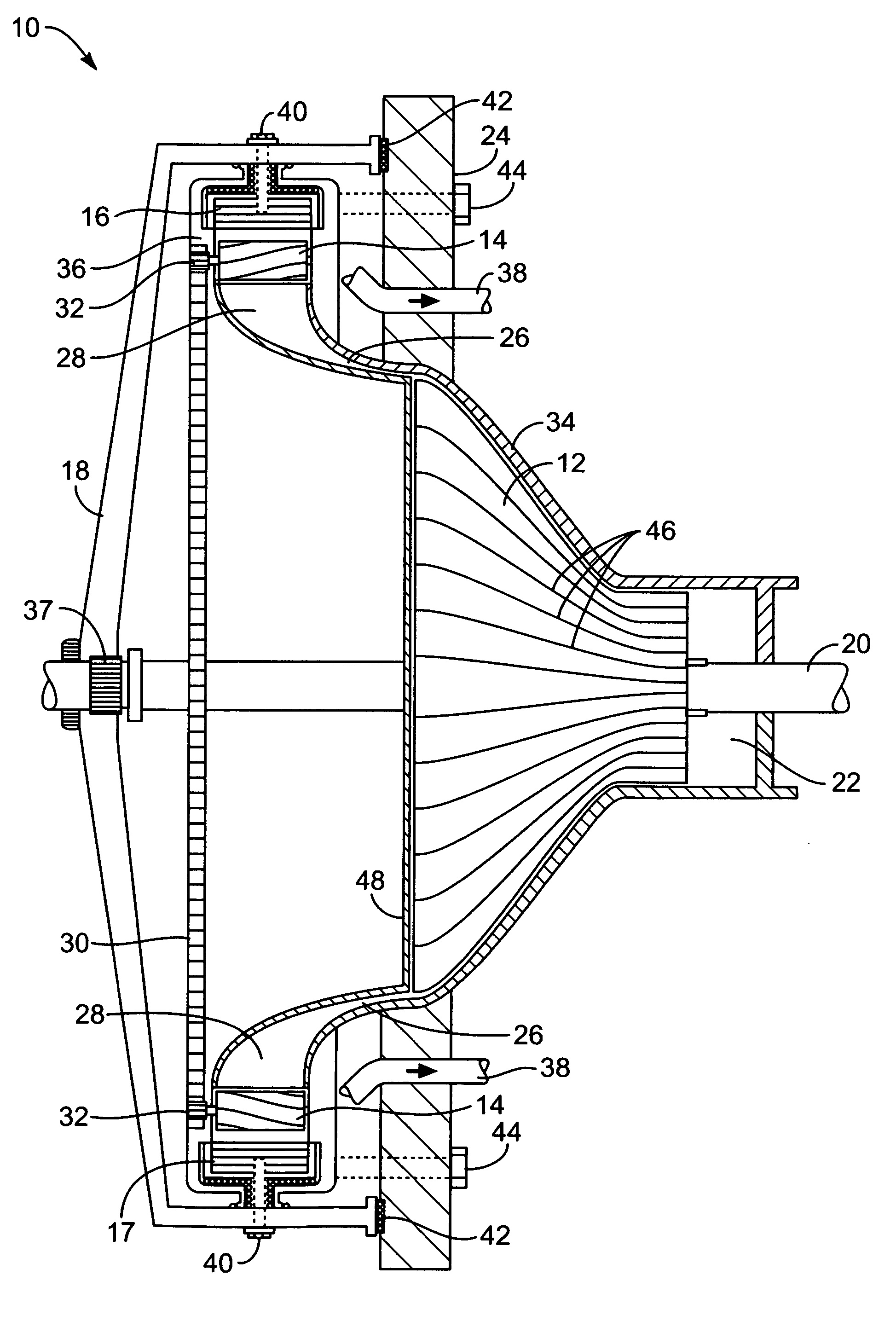
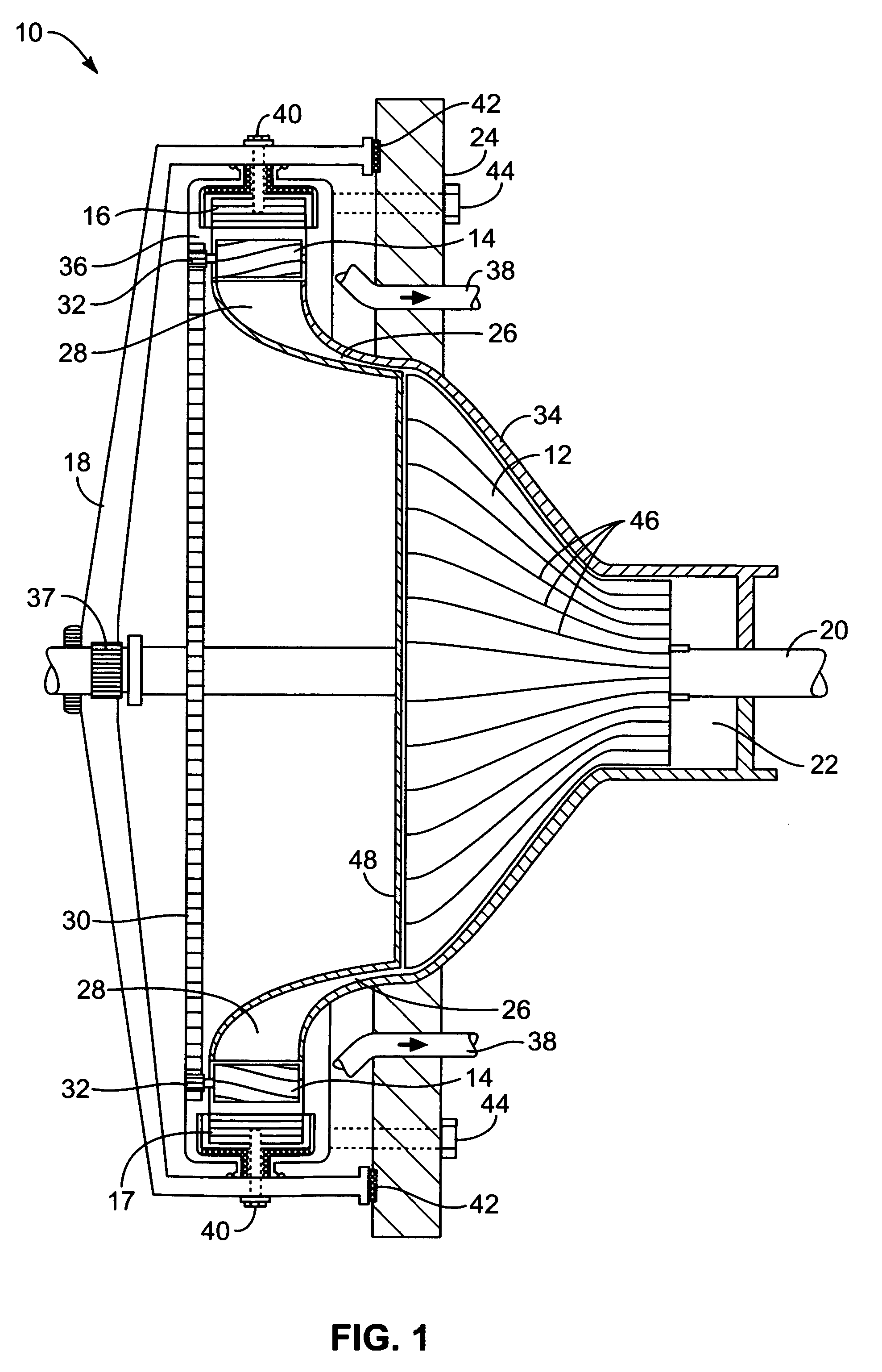
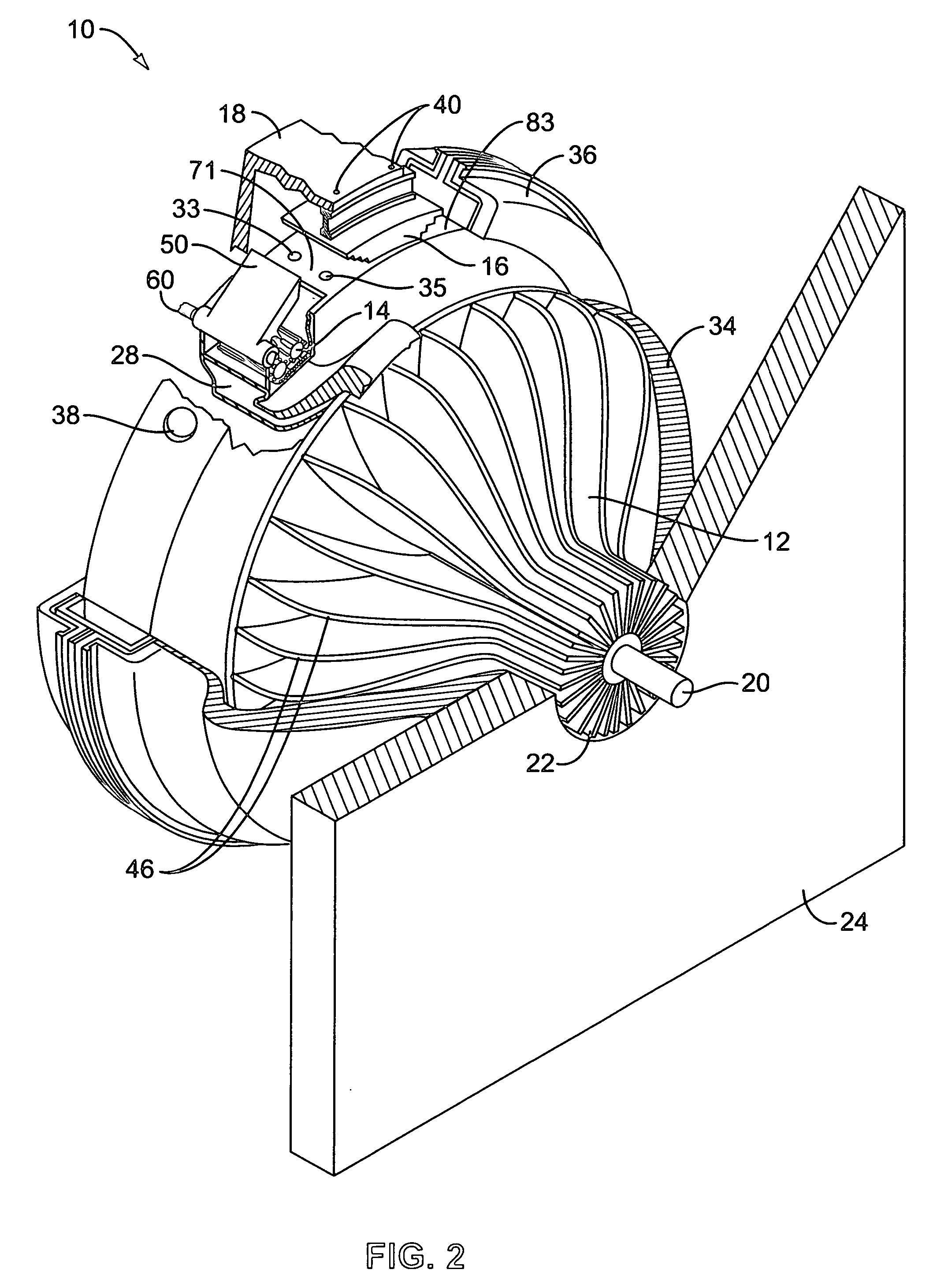
[0031] A novel engine is disclosed that is an improvement over the prior art. Engine 10 is illustrated in FIGS. 1 and 2 and is a multistage compression, air chamber trap engine with turbine like features that eschews reciprocating pistons found in conventional reciprocating piston combustion engines. Engine 10 includes a first compressor stage or compressor 12, which rotates within a compressor housing or shell 34, that is further coupled to two second compressor stages or compressors 14 via compressed air path 22. Compressor shell 34 connects to an engine frame 24, which provides support and rigidity for engine 10. Compressed air from path 26 feeds to an air feed 28 that is coupled to both second compressors 14. Each compressor 14 provides a second compression action on the compressed air and mixes fuel with it just prior to combustion, which is used to extract energy and convert the force into useable work.

[0032] Engine 10 further includes an active or first race piston 16 that t...


PUM


Abstract

A novel combustion engine with turbine like properties is disclosed. The novel engine (10) comprises an air intake, a first compressor stage, coupled to the air intake, a second compressor stage, coupled to the first compressor stage, a transfer valve, placed between the compressor stages and an annular race. Within the annular race, toroidal piston travels and passes over the transfer valve. The valve, toroidal piston and race form a temporary combustion chamber that expands as the piston travels within the annular race. Compressed air and fuel are introduced into the temporary combustion chamber and ignited to release the chemical energy and force the turbine piston to travel faster within the annular race. The first compressor stage is rotatably coupled to a crank shaft, which drives the first compressor stage and connects to an armature, which also connects the turbine piston so that useful work can be extracted from the energy released from the combustion of the fuel-air mixture.

Description

[0001] This patent application claims priority on U.S. Provisional Patent Application No. 60 / 546,577 filed Feb. 20, 2004, entitled “A NOVEL INTERNAL COMBUSTION TURBINE ENGINE,” and on U.S. patent application Ser. No. 11 / 009,493, filed Dec. 11, 2004, entitled “A NOVEL INTERNAL COMBUSTION TOROIDAL ENGINE,” both invented by Nicholas F. Mirabile, and PCT Patent Application No. PCT / US2005 / 005539, published Sep. 9, 2005, which is based on above U.S. patent applications, herein incorporated by reference for all purposes.BACKGROUND [0002] The present invention relates to internal combustion engines, namely, to an engine that isolates the combustion chamber from a compression chamber and directs the combusted fuel mixture tangentially against a drive wheel. [0003] There are many types of engines that have been developed over the past 250 years. The evolution of engines began with steam engines, which were an external combustion engine, but were dangerous and inefficient. Stirling engines wer...

Claims


Application Information

Patent Timeline
Patent Type & Authority Applications(United States)
IPC IPC(8): F02B57/08F01B13/06
CPCF01D1/22F02B33/36F02B33/38F02B37/04F02C5/06Y02T50/672Y02T10/144Y02T10/12Y02T50/60
Inventor MIRABILE, NICHOLAS F.
Owner MIRABILE NICHOLAS F
Learn More