Eureka AIR delivers breakthrough ideas for toughest innovation challenges, trusted by R&D personnel around the world.

Heat exchanger and method of manufacturing outside plate used for header tanks of heat exchanger

Inactive Publication Date: 2007-06-14
SHOWA DENKO KK
View PDF0 Cites 23 Cited by
  • Summary
  • Abstract
  • Description
  • Claims
  • Application Information

AI Technical Summary

Benefits of technology

[0005] An object of the present invention is to solve the above problem and to provide a heat exchanger which has a reduced weight and whose header tanks have a sufficient withstanding pressure, and a method of manufacturing an outside plate used for header tanks of a heat exchanger.

Problems solved by technology

However, in this case, the weight of the heat exchanger increases.

Method used


Image

  • Heat exchanger and method of manufacturing outside plate used for header tanks of heat exchanger
  • Heat exchanger and method of manufacturing outside plate used for header tanks of heat exchanger
  • Heat exchanger and method of manufacturing outside plate used for header tanks of heat exchanger

Examples


Embodiment Construction

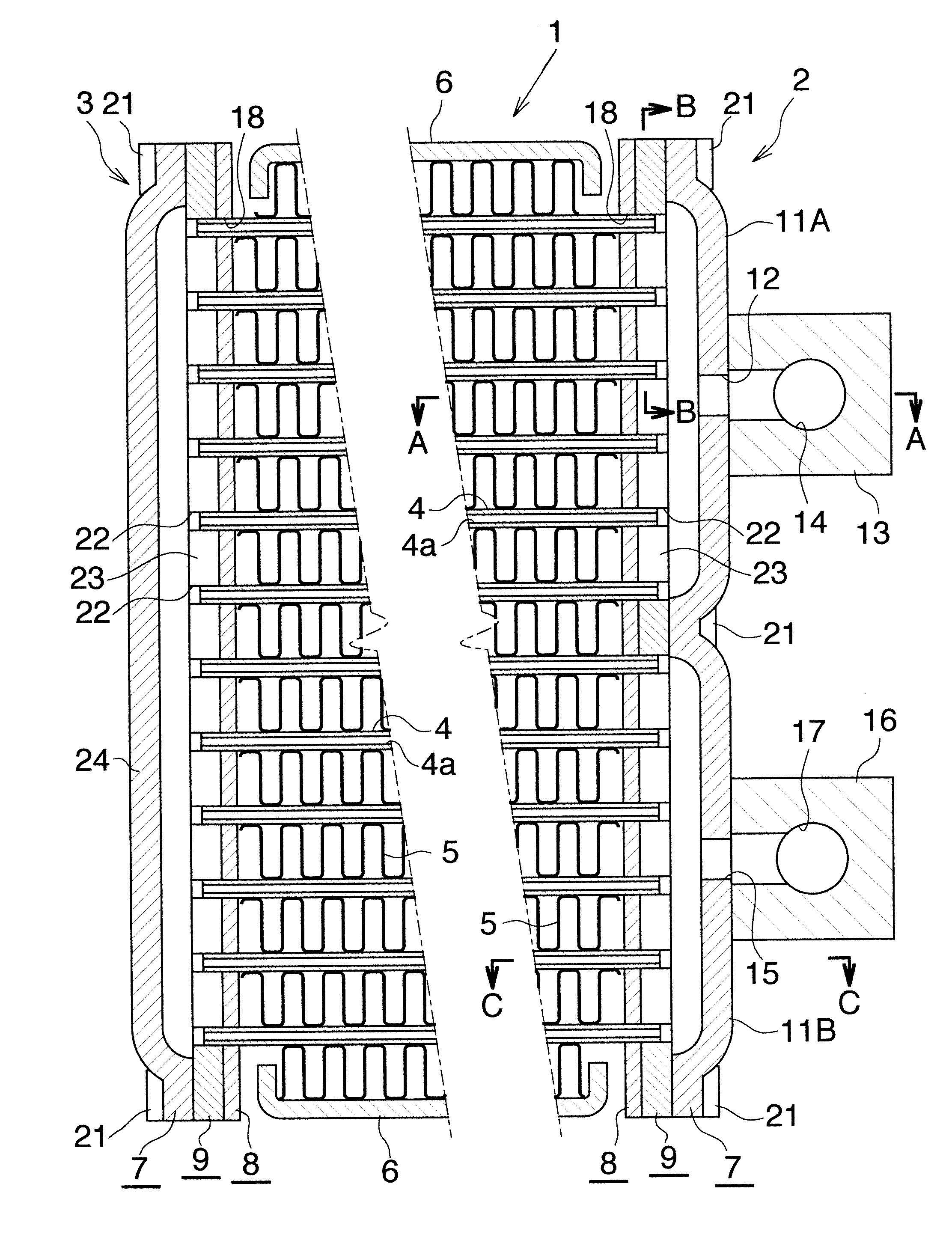
[0053] Embodiments of the present invention will next be described in detail with reference to the drawings. These embodiments are implemented by applying a heat exchanger according to the present invention to a gas cooler of a supercritical refrigeration cycle.

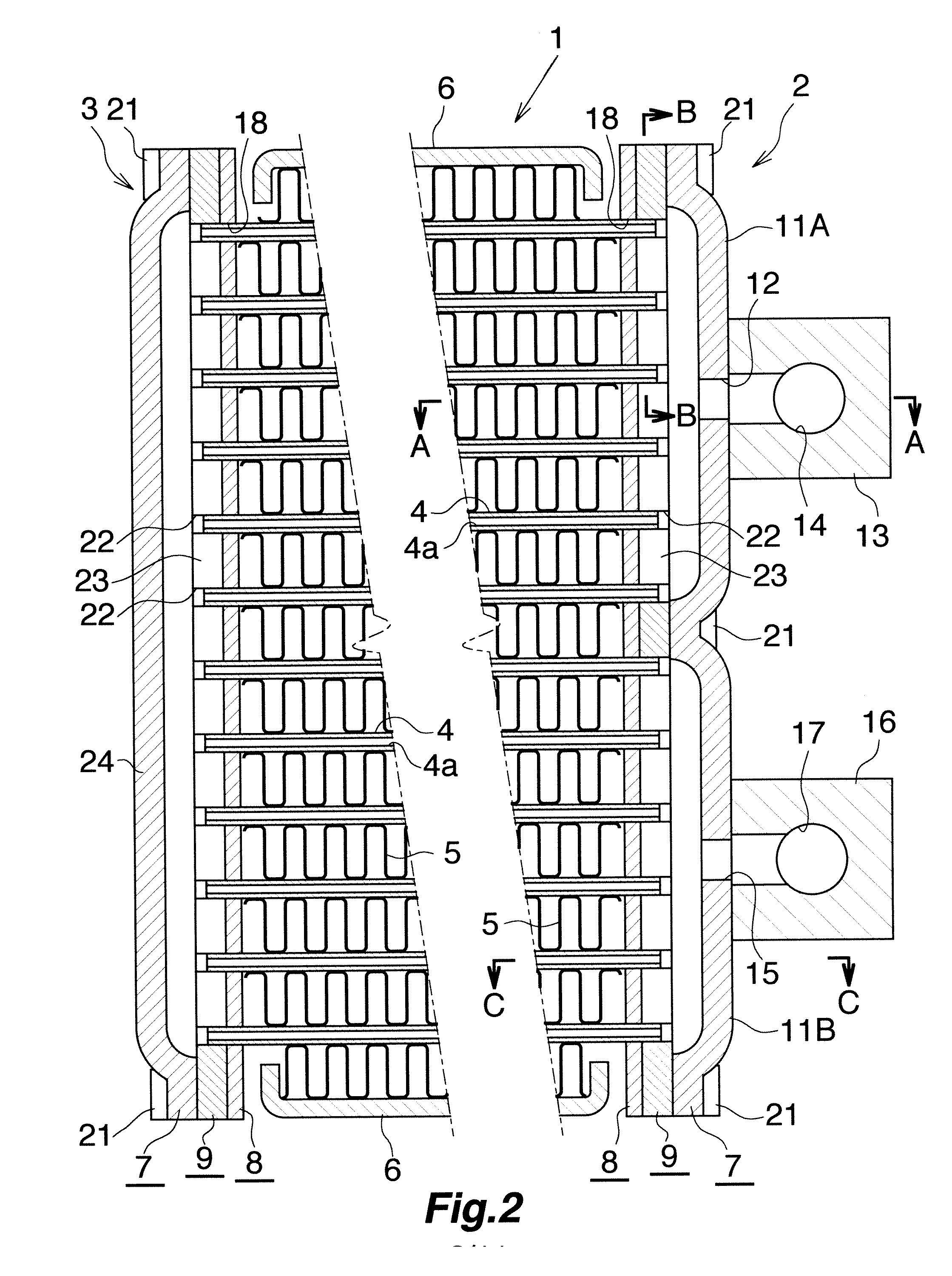
[0054] In the following description, the upper, lower, left-hand, and right-hand sides of FIGS. 1 and 2 will be referred to as “upper,”“lower,”“left,” and “right,” respectively. Further, in the following description, the term “aluminum” encompasses aluminum alloys in addition to pure aluminum.

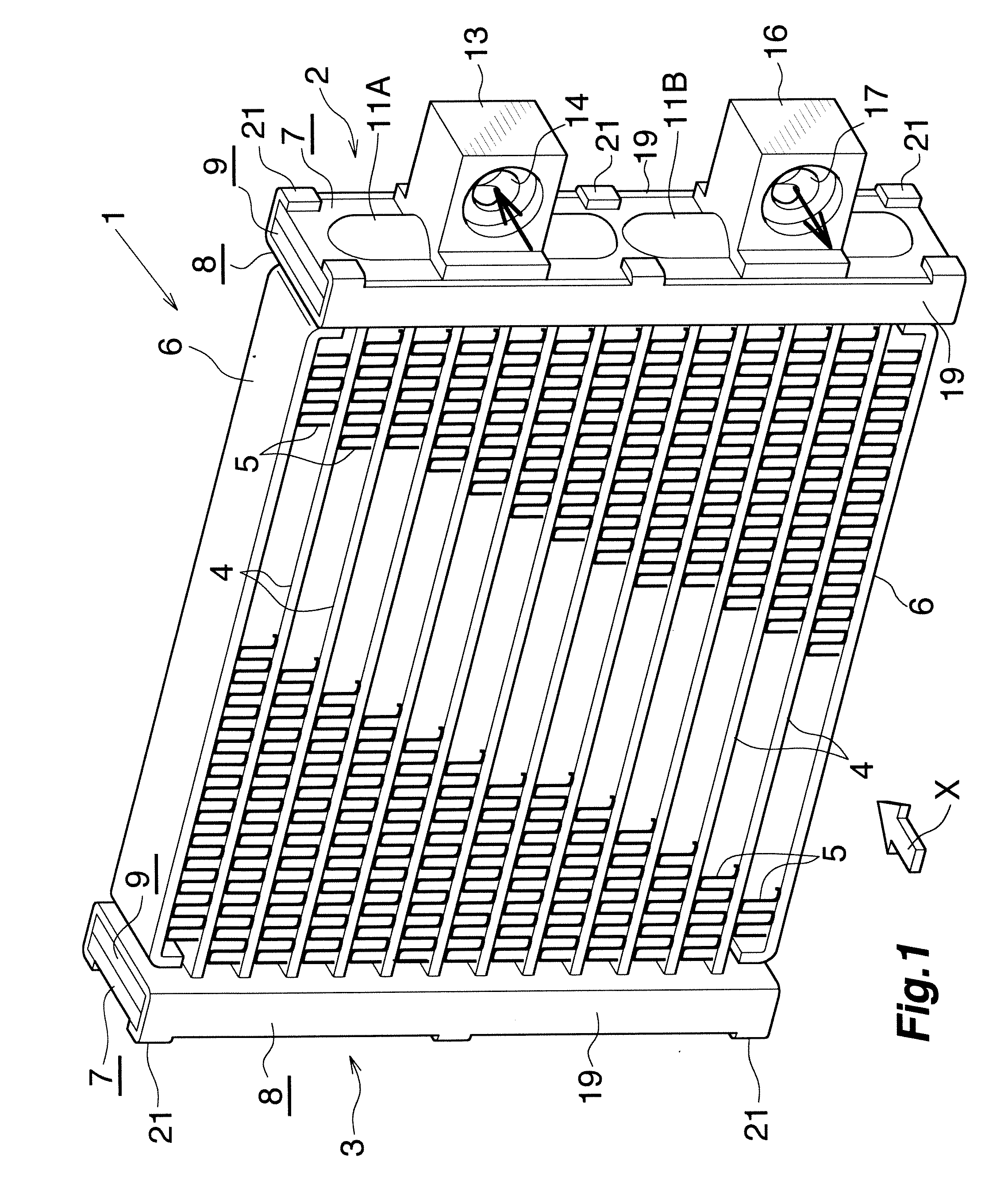
[0055]FIGS. 1 and 2 show the overall construction of a gas cooler to which the heat exchanger according to the present invention is applied. FIGS. 3 to 6 show the configuration of essential portions of the gas cooler of FIG. 1. FIGS. 7 to 9 show a method of manufacturing header tanks. FIGS. 10 and 11 show a heat exchange tube. FIG. 12 shows a method of manufacturing the heat exchange tube.

[0056] With reference to FIG. 1, a gas cooler ...


PUM


Abstract

A method of manufacturing an outside plate used for a heat exchanger header tank configured such that an outside plate having an outwardly bulging portion, an inside plate, and an intermediate plate are brazed together in layers. A thick portion is formed on an outside-plate forming metal plate at a center portion with respect to the width direction thereof. Subsequently, a press work is performed on the outside-plate forming metal plate so as to form the outwardly bulging portion by making use of the thick portion. A connection portion having a curvature radius of 1 mm or less is formed between an inner wall surface of the outwardly bulging portion and each of surfaces of the outside plate located on the opposite sides of the outwardly bulging portion. This method enables manufacture of an outside plate which reduces the weight while securing sufficient withstanding pressure.

Description

BACKGROUND OF THE INVENTION [0001] The present invention relates to a heat exchanger and a method of manufacturing an outside plate used for header tanks of a heat exchanger. More particularly, the present invention relates to a heat exchanger that can be favorably used as a gas cooler or an evaporator of a supercritical refrigeration cycle in which a CO2 (carbon dioxide) refrigerant or a like supercritical refrigerant is used, and to a method of manufacturing an outside plate used for header tanks of such a heat exchanger. [0002] Herein and in the appended claims, the term “supercritical refrigeration cycle” means a refrigeration cycle in which a refrigerant on the high-pressure side is in a supercritical state; i.e., assumes a pressure in excess of a critical pressure. The term “supercritical refrigerant” means a refrigerant used in a supercritical refrigeration cycle. Also, herein and in the appended claims, the downstream side of flow (represented by arrow X in FIG. 1) of air th...

Claims


Application Information

Patent Timeline
IPC IPC(8): F28B1/00
CPCF28D1/0391F28D1/05391F28D2021/0071F28D2021/0073F28F1/022F28F9/0224F28F9/0246
Inventor MINAMI, KAZUHIKOSASAKI, HIRONAKAIGAWA, SHUNSUKE
Owner SHOWA DENKO KK
Why Eureka
Eureka Blog
Learn More