Wing/winglet configuration and aircraft including it

a technology of winglet and configuration, which is applied in the direction of aircraft control, airflow influencers, aircraft components, etc., can solve the problems of excessive fuel consumption of aircraft and very strong drag, and achieve the effects of reducing aircraft consumption, reducing drag of the wing, and increasing rang

Inactive Publication Date: 2007-06-14
DASSAULT AVIATION
View PDF7 Cites 40 Cited by
  • Summary
  • Abstract
  • Description
  • Claims
  • Application Information

AI Technical Summary

Benefits of technology

[0014] In fact, there has been observed a significant reduction in the drag of the wing according to the invention, in particular in transonic cruising mode. Now this drag which increases very strongly with the speed in the vicinity of transonic modes is a factor in excess fuel consumption by the aircraft. The wing according to the invention therefore enables the consumption of the aircraft to be reduced and consequent

Problems solved by technology

Now this drag which increases very strongly with the speed in the vicinity

Method used


Image

  • Wing/winglet configuration and aircraft including it
  • Wing/winglet configuration and aircraft including it
  • Wing/winglet configuration and aircraft including it

Examples


Embodiment Construction

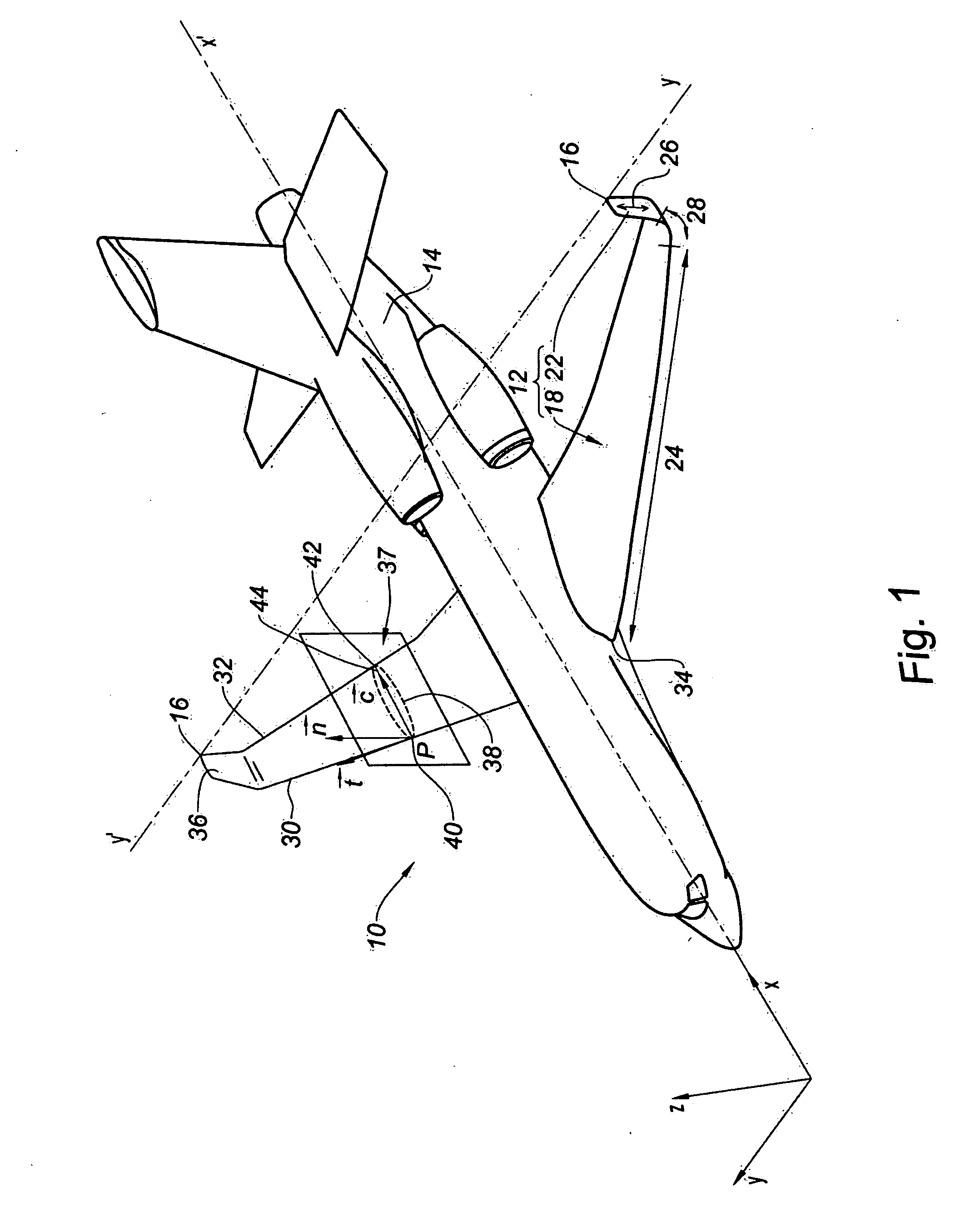
[0033]FIG. 1 is referred to here, in which is represented a stationary aircraft 10 on which are mounted two wing 12 / winglet configurations according to the invention.

[0034] The axis X-X′ is defined as being the median axis of the fuselage 14 of the aircraft 10 and the axis Y-Y′ as being the axis joining the end points 16 of each of the two wings 12.

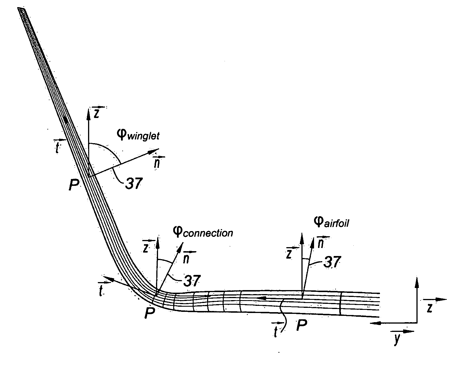
[0035] The direct orthogonal system of axes ( x, y, z) is then defined in which:

[0036] the vector x is a director vector of the axis X-X′ oriented in the direction of the rear of the aircraft 10;

[0037] the vector y is a director vector of an axis parallel to the axis Y-Y′ determined in such a manner that the system of axes ( x, y, z) is effectively a direct orthogonal system of axes; and

[0038] the vector z is perpendicular to the plane defined by the vectors x and y, oriented toward the top of the aircraft 10.

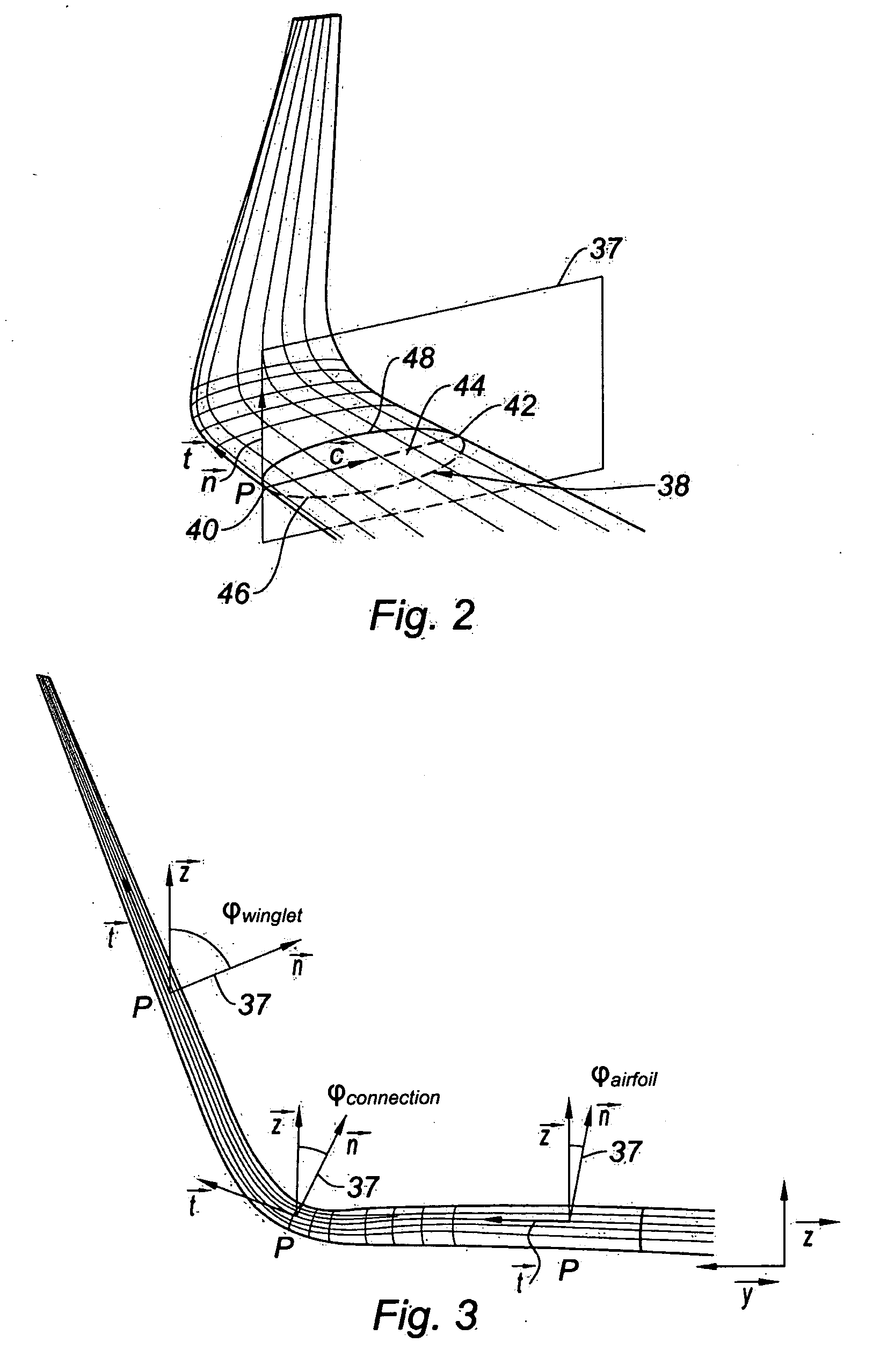
[0039] A wing 12 / winglet configuration according to the invention includes an airfoil 18 and a winglet 22 that define an airf...


PUM


Abstract

A wing/winglet configuration includes an airfoil and a winglet disposed at one end of said airfoil, said airfoil and said winglet defining an airfoil zone, a winglet zone and a connecting zone of connection of the winglet and the airfoil, a portion of the upper surface of the profile being flattened, in at least one part of said connecting zone, relative to the same portion of the upper surface of the profile of the airfoil zone, said flattened portion in at least one part of said connecting zone being a central portion of the upper surface of the profile. The invention relates also to an aircraft including such a wing/winglet configuration.

Description

BACKGROUND OF THE INVENTION [0001] 1. Field of the Invention [0002] The invention relates to a wing / winglet configuration, in particular for aircraft, and to an aircraft including such a wing / winglet configuration. [0003] 2. Description of the Prior Art [0004] It is known to provide an aircraft wing with a winglet disposed at one end of the airfoil in order to reduce the drag of the aircraft. [0005] The airfoil and the winglet respectively define an airfoil zone and a winglet zone that are linked by a zone of connection of the winglet and of the airfoil. [0006] Conventionally, the profiles of the airfoil zone feature a convex and domed upper surface whereas their lower surface includes a convex first portion extending from the leading edge and a concave second portion extending to the trailing edge. [0007] Conventionally, the profiles of the winglet zone also feature a convex and domed upper surface, whereas their lower surface includes a convex first portion extending from the lead...

Claims


Application Information

Patent Timeline
IPC IPC(8): B64C5/06
CPCB64C3/10B64C3/14B64C5/08B64C23/065B64C2003/144Y02T50/12Y02T50/164B64C23/069Y02T50/10
Inventor JOHAN, ZDENEK
Owner DASSAULT AVIATION
Why Eureka
Try Eureka