Adjustable hanger bar assembly with bendable portion

Active Publication Date: 2007-06-14
SIGNIFY NORTH AMERICA CORP
View PDF6 Cites 60 Cited by
  • Summary
  • Abstract
  • Description
  • Claims
  • Application Information

AI Technical Summary

Benefits of technology

[0012] According to a first embodiment, an adjustable mounting bar assembly for a luminaire fixture comprises a first bar adapted to be slidably received within a second bar portion, an arm bendably positioned at an end of one of the first bar or the second bar, a relief area disposed between the first arm and the one of the first bar or the second bar, the first bar and the second bar telescoping between a first minimized length and a second extended length. The arm is bendable to an extended position to provide increased length to said adjustable mounting bar assembly. The arm is bendable to extend the length of the adjustable mounting bar assembly and maintain engagement between the first bar and the second bar. The arm bendable from a first position substantially perpendicular to the one of the first bar or the second bar to a second position substantially parallel to the one of the first bar or the second bar. The arm has a notch for receiving a suspended ceiling grid. The adjustable mounting bars for a luminaire fixture further comprises a pivoting arm at the other of the first bar or the second bar. The second arm is pivotally connected to the other of the first bar or the second bar.
[0013] According to a second embodiment, a telescoping hanger bar assembly for a luminaire fixture assembly comprises a channel shaped to slidably receive a bar, a pre-stressed relief area disposed at an end of the bar and a first foot portion extending from the relief, the arm portion moveable at the relief from a folded position disposed at an angle to the one of the first bar and the second bar to substantially parallel to the one of the first bar member and the second bar member, the foot portio

Problems solved by technology

Two problems which are generally incurred when utilizing two-piece hanger bar constructions are a lack of stability and failure to provide support for the recessed fixture when the hanger bars are extended to

Method used


Image

  • Adjustable hanger bar assembly with bendable portion
  • Adjustable hanger bar assembly with bendable portion
  • Adjustable hanger bar assembly with bendable portion

Examples


first embodiment

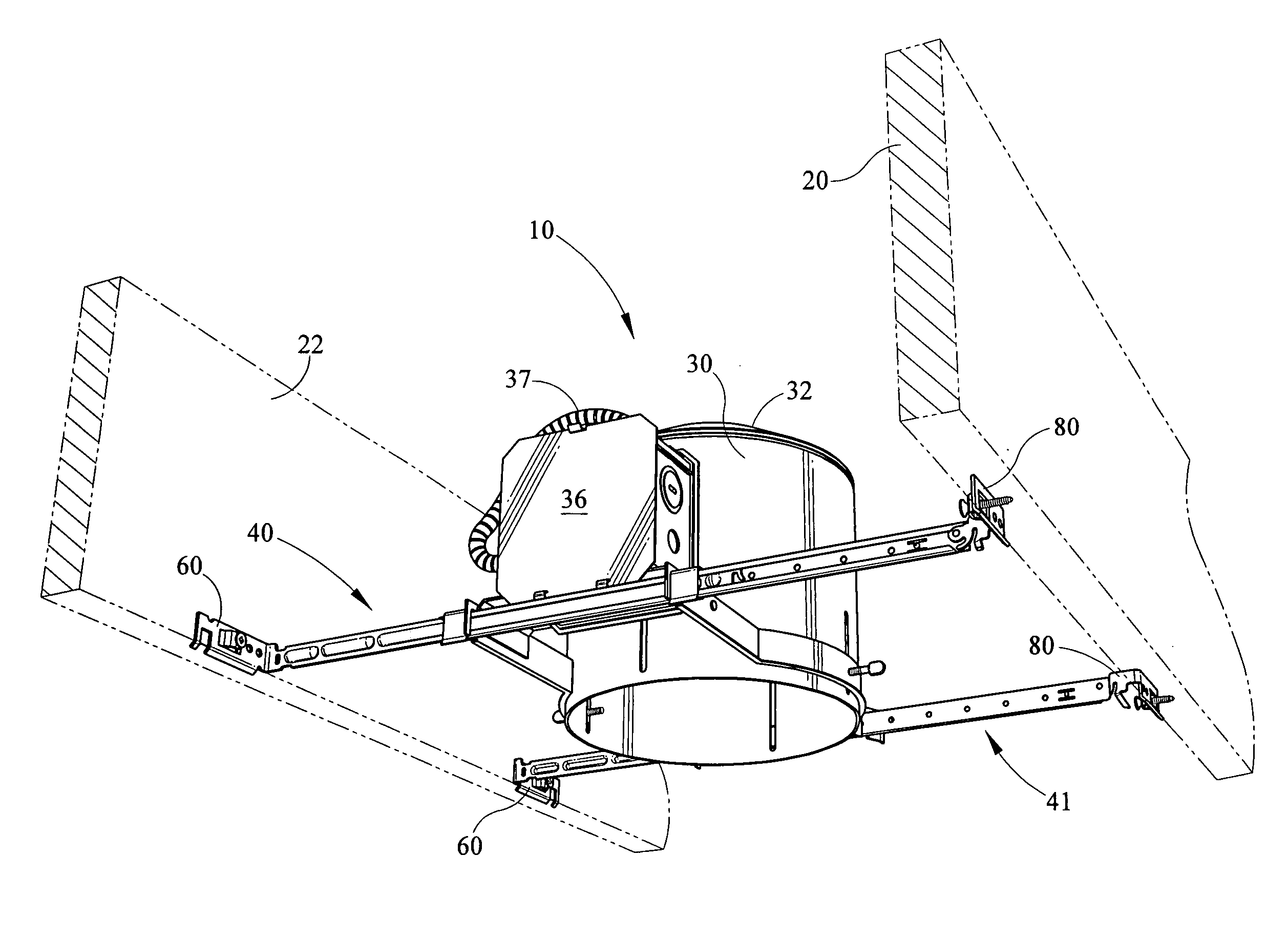
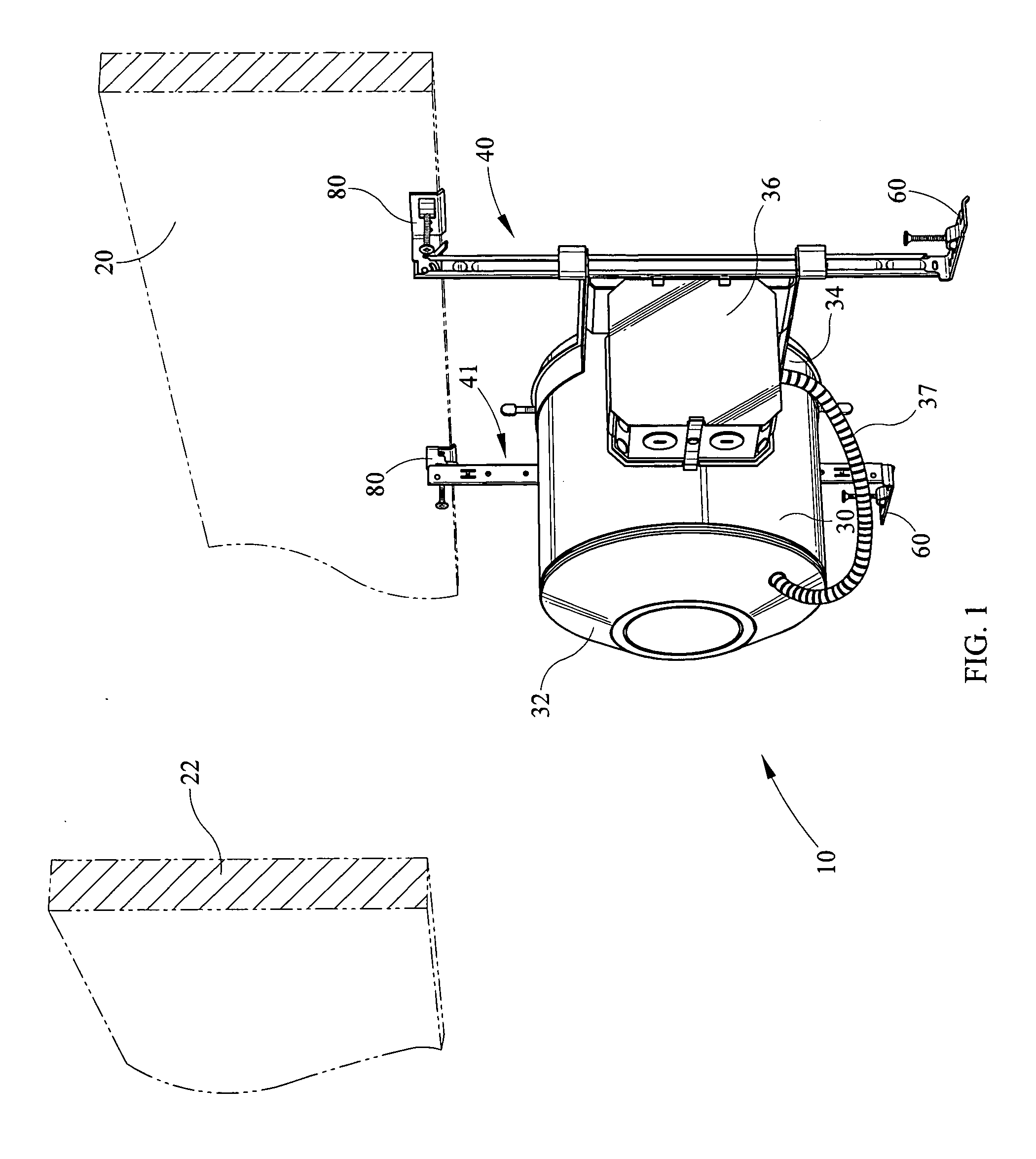
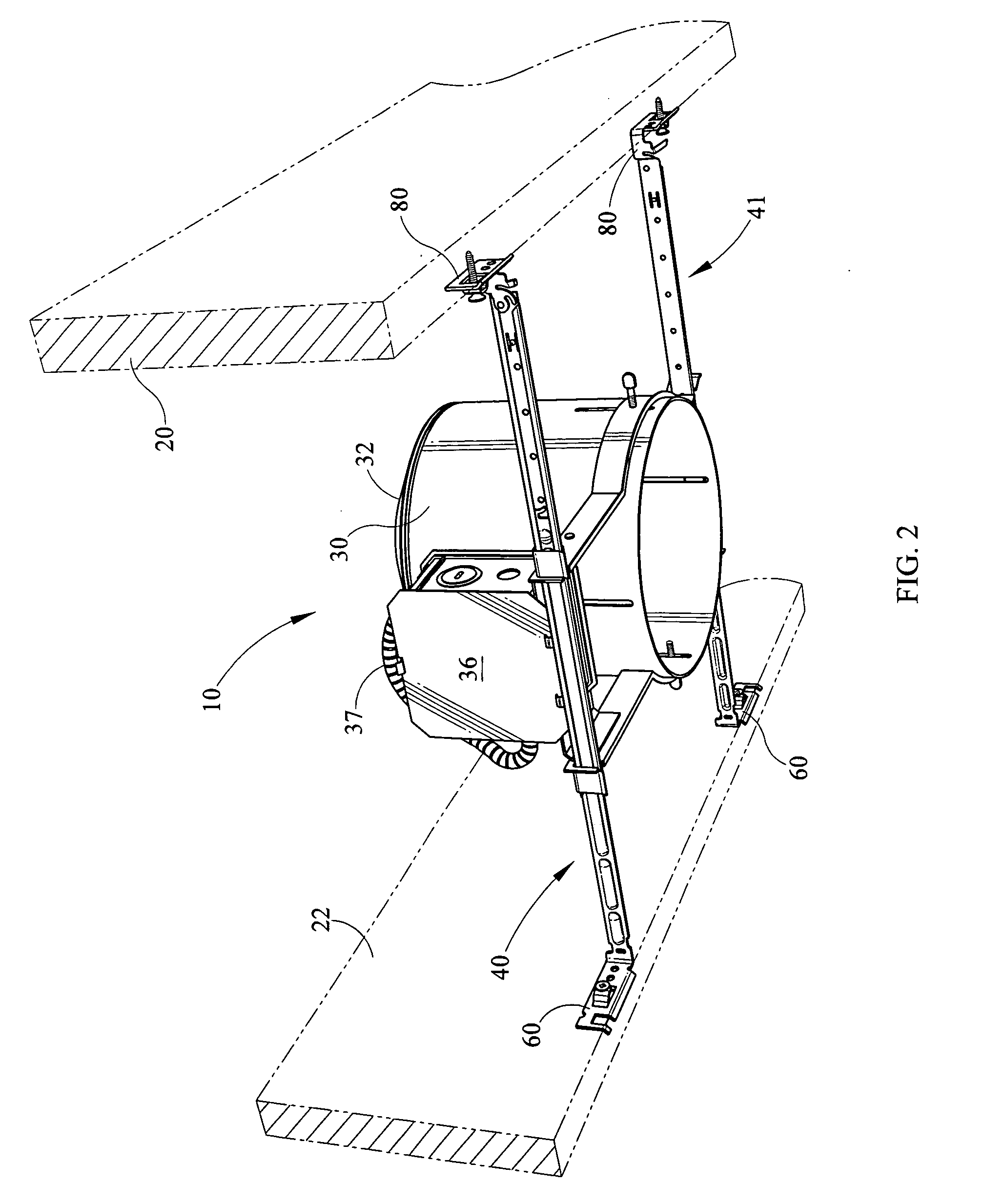
[0045] In operation, according to connection, the feet 80 are abutted against a lower edge of the joist 20 as shown in FIG. 1. Once the feet 80 are fastened to the joist 20, the force of gravity causes the frame-in kit 10 to pivot at the connection of the feet 80 and the second bars so that the hanger bar assemblies 40, 41 are generally hanging downwardly. In this position, the engagement of the opposed pivot hooks inhibits the hanger bar assemblies 40, 41 from sliding downwardly. From this position, an installer uses the junction box 36 to connect the power source to the wiring extending into the housing 30. Once the wiring connections are made within the junction box 36 and the lighting socket and light source are disposed within the can 30, the frame-in kit 10 is pivoted at the feet 80 into a position shown in FIG. 2. From this position, the opposed feet 60 may be engaging the second joist 22. Specifically, the joist lip 62 (FIG. 3) on the opposed feet 60 engage the lower edge of...

second embodiment

[0046] Referring now to FIG. 13, according to connection, opposed T-bars 120, 122 are shown which define, in part, portions of a suspended ceiling. The housing 30 and other portions of the frame-in kit 10 are removed for clarity to depict the adjustable hanger bar assemblies 40, 41. At one end, of the hanger bar assemblies, the feet 80 are connected to the T-grid 120 by receiving a feature of an upper portion of the grid within the notch 84. In order to secure the hanger bar assemblies 40, 41 to the T-grid 120, each foldable catch 90 is bent to engage the T-grid 120 and lock the adjustable hanger bar assemblies 40, 41 to the T-grid 120. Next, the bars 42 are slidably extended within the channels 70 until the appropriate length is obtained to span the distance between the first T-grid 120 and the second T-grid 122 of the suspended ceiling structure. According to one embodiment, the bead 78 of the channel 70 may engage the end of the third boss 54. Finally, the feet 60 are folded alon...


PUM


Abstract

The present invention is an adjustable hanger bar assembly for a light fixture. The assembly maintains structural integrity between first and second bars to support a recessed light fixture while being extended to distances where typical mounting assemblies fail. The hanger bar assembly comprises first and second bars which slidably engage one another. One of the first and second bars comprises a foldable foot which may be extended to increase the length of the hanger bar assembly.

Description

CROSS REFERENCES TO RELATED APPLICATIONS [0001] None. STATEMENT REGARDING FEDERALLY SPONSORED RESEARCH OR DEVELOPMENT [0002] None. REFERENCE TO SEQUENTIAL LISTING, ETC. [0003] None. BACKGROUND [0004] 1. Field of the Invention [0005] The present invention relates generally to a recessed light mounting bar assembly, and more specifically to an adjustable mounting bar for mounting a light fixture within a suspended ceiling grid or joist structure. [0006] 2. Description of the Related Art [0007] Recessed downlight fixtures have become increasingly popular for residential and commercial use. One reason for the increased popularity is that the recessed downlight fixtures meet a wide range of interior lighting requirements while also being aesthetically pleasing. Recessed lighting fixtures or downlights provide lighting for an area and are aesthetically pleasing due in part to the unobtrusive nature of the fixtures themselves which are typically recessed within the ceiling. Further, recess...

Claims


Application Information

Patent Timeline
IPC IPC(8): F16M11/00
CPCF21V21/04Y10S248/906
Inventor NEVERS, CRAIG S.WEDEKIND, ROBERT J.
Owner SIGNIFY NORTH AMERICA CORP
Why Eureka
Try Eureka