Electric power generation system

a technology of electric power generation and wind power, applied in the direction of electric generator control, greenhouse gas reduction, sustainable manufacturing/processing, etc., can solve the problems of inability to take advantage of economic scale, limited current wind power generation methods, and undesirable wind power, etc., and achieve the effect of reliable power supply to the electric grid

Inactive Publication Date: 2007-06-14
GALAYDA STEPHEN +1
View PDF6 Cites 44 Cited by
  • Summary
  • Abstract
  • Description
  • Claims
  • Application Information

AI Technical Summary

Benefits of technology

[0009] The disclosed embodiments of the present invention are directed to a hybrid electric generating system configured to use the force of wind to drive wind pumps that pump fluid in a hydraulic system for driving a hydroelectric generator. In one embodiment, the wind pump has an adjustable blade assembly for controlling blade boundary characteristics and blade pitch and the system has a standby-pump system to pump fluid in the hydraulic system when the wind is insufficient to power the system. In another embodiment, the wind pump has an inductive power supply to provide power to the adjustable blade assembly. An efficient and adaptable control system is employed, enabling the generating system to reliably provide power to an electric grid.

Problems solved by technology

Current wind-powered electric generating methods are limited by several disadvantages that have historically made wind power an undesirable primary or alternate source of energy for large utilities.
The disadvantages include an inability to take advantage of economy of scale, duplication of systems, high maintenance costs, and an inability to provide large blocks of reliable, firm power.

Method used


Image

  • Electric power generation system
  • Electric power generation system
  • Electric power generation system

Examples


Embodiment Construction

[0031] The present invention provides for a hybrid electric generator having an efficient transmission system. Embodiments of the invention will be described using a limited number of representative examples and drawings.

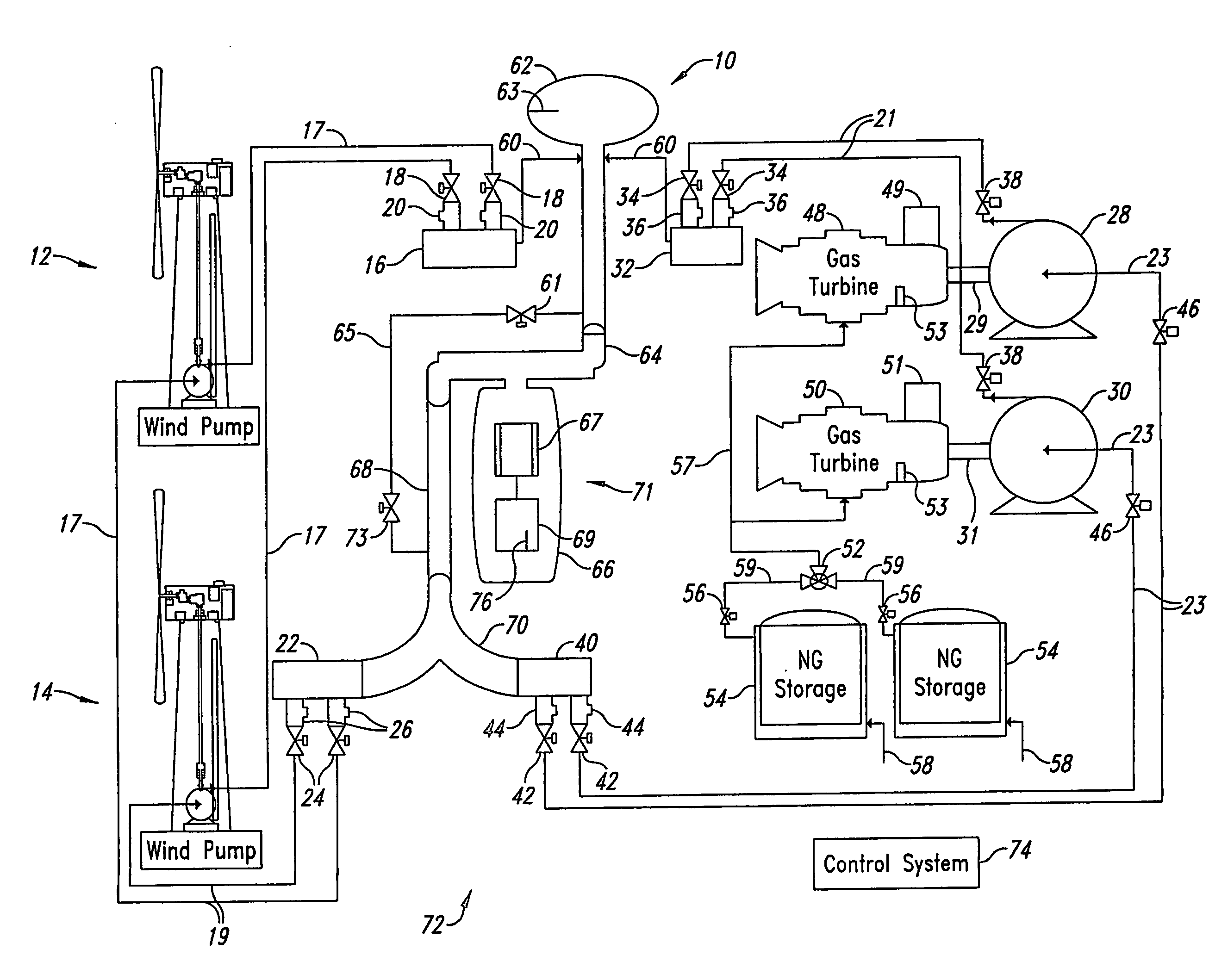
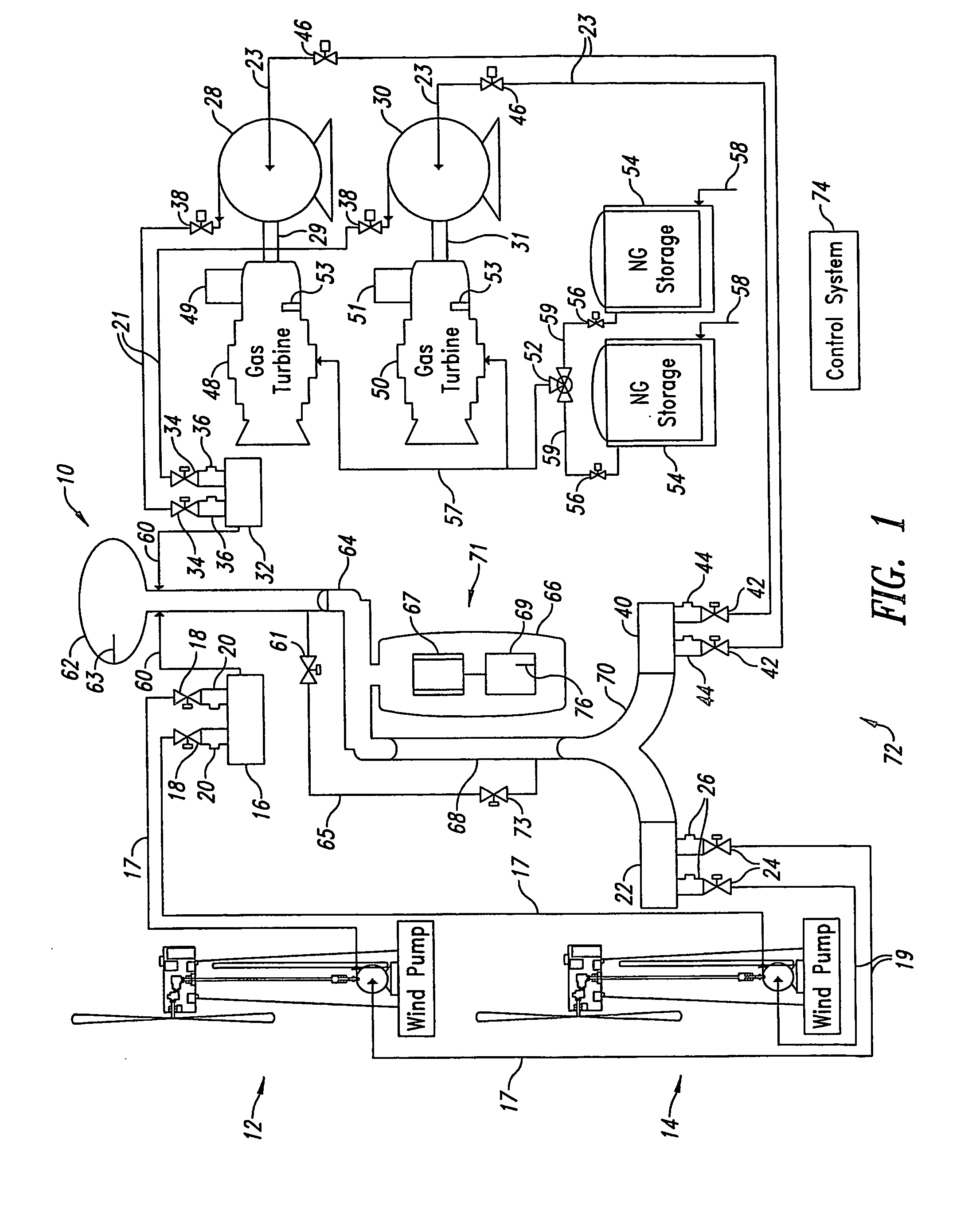
[0032] Referring initially to FIG. 1, shown therein is a hybrid electric power generating system 10. The system 10 includes first and second wind pumps 12, 14, each of which is coupled to a first supply or inlet manifold 16 through a pipe 17. Associated with the pipe 17 are a flow control valve 18 and a flow sensor 20. The first and second wind pumps 12, 14 are also coupled to a first suction or outlet manifold 22 through a pipe 19, that has associated with it a flow control valve 24 and a flow sensor 26. A single wind pump or additional wind pumps (not shown) may be employed. As discussed in more detail below, the wind pumps 12, 14 pump fluid, and the flow control valves 18, 24, may be configured to open and close manually, either in response to control signals or...


PUM


Abstract

An electric generating system configured to use the force of wind to drive at least one wind pump that pumps fluid in a hydraulic system for driving a hydroelectric generator. The wind pump has a blade assembly with blade boundary characteristic and pitch controls. The wind pump includes an inductive power supply. A standby-pump provides pressurized fluid in the hydraulic system when the wind is insufficient to power the system. An efficient and adaptable control system is employed, enabling the generating system to reliably provide power to an electric grid.

Description

BACKGROUND OF THE INVENTION [0001] 1. Field of the Invention [0002] The present invention is directed to an electric power generation system, and more particularly, to a wind-based hybrid electric power generation system that is efficient and reliable. [0003] 2. Description of the Related Art [0004] Wind-driven generators are transducers that utilize moving air to generate electrical energy. In a typical wind-generator system, an impeller is driven by the wind, which in turn drives a transmission system to achieve a mechanical advantage for driving a device to generate electricity, such as a direct current electrical generator or an alternator. [0005] An example of a known wind-driven generator system is discussed in U.S. Pat. No. 2,539,862 issued to Rushing (“Rushing”). Rushing uses a wind wheel or impellers to drive a plurality of pumps or compressors. The pumps or compressors pump a fluid that is stored under pressure. The pressurized fluid is used to operate an electrical genera...

Claims


Application Information

Patent Timeline
Patent Type & Authority Applications(United States)
IPC IPC(8): F03D9/00H02P9/04F03D9/02
CPCF01D15/08F02C1/007F02C1/08F02C3/20F02C6/14F03D7/0224F03D7/0232F03D7/0236F03D9/00F03D9/008F03D9/025F03D9/028F05B2220/704F05B2240/31F05B2240/52F05B2240/54F05B2260/90F05B2270/328H01F38/18H01F2038/143H04B5/0037H04B5/0093H04B2203/5458Y02E10/721Y02E10/723Y02E10/725Y02E60/15Y02E60/17F05D2220/74F05D2240/52F05D2240/54F05D2260/90F03D9/14F03D9/17Y02E10/72Y02E60/16Y02E70/30Y02P80/10F03D9/28F03D9/255
Inventor GALAYDA, STEPHENGALAYDA, MICHAEL
Owner GALAYDA STEPHEN
Why Eureka
Try Eureka