
Surface acoustic wave apparatus and manufacturing method therefor

a surface acoustic wave and a manufacturing method technology, applied in the direction of piezoelectric/electrostrictive/magnetostrictive devices, electrical apparatus, piezoelectric/electrostriction/magnetostriction machines, etc., can solve the disadvantage of resist stripper b>63/b>, the inability to use the saw resonator, and the considerable deterioration of characteristics. , to achieve the effect of suppressing

Inactive Publication Date: 2007-06-14
MURATA MFG CO LTD
View PDF14 Cites 20 Cited by
  • Summary
  • Abstract
  • Description
  • Claims
  • Application Information

AI Technical Summary

Benefits of technology

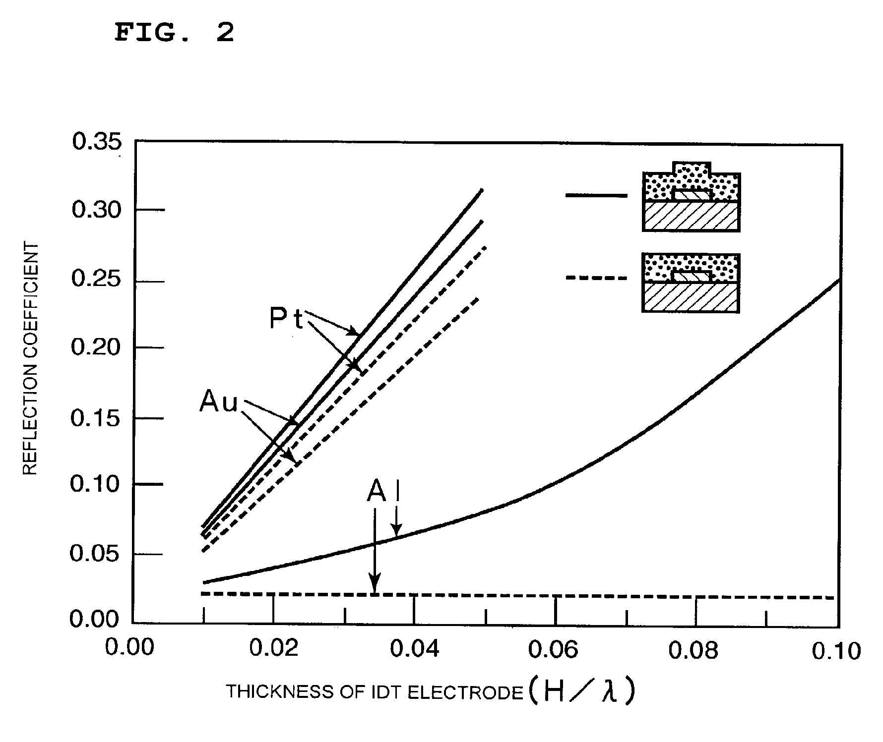
The present invention provides a SAW apparatus with improved resonance and filter characteristics. The invention achieves this by forming an insulating layer between the electrodes and the IDT electrode to increase the reflection coefficient of the IDT electrode and decrease ripples in the resonance and antiresonance characteristics. The invention also provides a manufacturing method for this SAW apparatus. The SAW apparatus has superior characteristics, such as a large reflection coefficient, high flexibility in selecting the material forming the IDT electrode, and a decreased possibility of erosion of the IDT electrode. The invention also provides a SAW apparatus with a protective metal film and insulating layers to suppress ripples in the resonance and filter characteristics. The invention can be used in various types of SAW resonators and filters. The electrode may be an IDT electrode or a reflector. The piezoelectric substrate may be a LiTaO3 substrate or a reflector. The thickness of the electrode and insulating layers may be about the same or the protective metal film may be thicker than the electrode. The invention also provides a method for manufacturing the SAW apparatus with improved TCF.

Problems solved by technology

In this case, the IDT electrode 63 may be disadvantageously eroded by the resist stripper.
However, a considerable deterioration in the characteristics after the formation of the SiO2 film was observed, and the present inventors found that this SAW resonator cannot be put to practical use.
Accordingly, a sufficient stop band cannot be achieved, causing the generation of sharp ripples in the vicinity of the antiresonant frequency.

Method used


Image

  • Surface acoustic wave apparatus and manufacturing method therefor
  • Surface acoustic wave apparatus and manufacturing method therefor
  • Surface acoustic wave apparatus and manufacturing method therefor

Examples


Embodiment Construction

[0153] The present invention is described in detail below with reference to the accompanying drawings through illustration of preferred embodiments of the present invention.

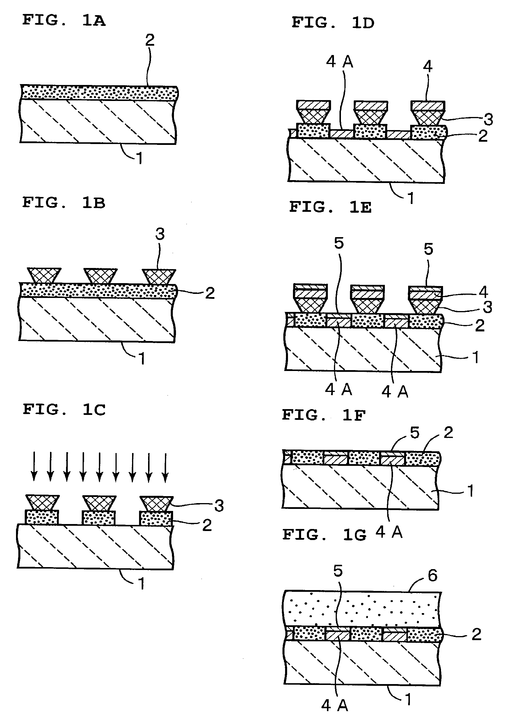
[0154] A manufacturing method for a SAW apparatus according to a first preferred embodiment of the present invention is described below with reference to FIGS. 1A through 1G, and 6.

[0155] As shown in FIG. 1A, a LiTaO3 substrate 1 is first prepared as a piezoelectric substrate. In the first preferred embodiment of the present invention, a 36°-rotated Y-plate X-propagating LiTaO3 substrate having Euler angles (0°, 126°, 0°) is preferably used. As the piezoelectric substrate, a LiTaO3 substrate having different crystal orientations may be used, or a substrate made of another piezoelectric single crystal may be used. Alternatively, a piezoelectric substrate formed by laminating piezoelectric thin films on an insulating substrate may be used. Θ of the Euler angles (φ, Θ, ψ) can be expressed by Θ=cut angle+90°.

[0156...


PUM

PropertyMeasurementUnit
reflection coefficientaaaaaaaaaa
Euler anglesaaaaaaaaaa

Abstract

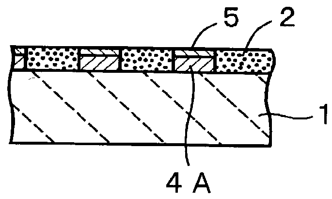
In a manufacturing method for a SAW apparatus a first insulating layer is formed on the entire surface of a piezoelectric LiTaO3 substrate. By using a resist pattern used for forming an IDT electrode, the first insulating layer in which the IDT electrode is to be formed is removed. An electrode film made of a metal having a density higher than Al or an alloy primarily including such a metal is disposed in the area in which the first insulating layer is removed so as to form the IDT electrode. The resist pattern remaining on the first insulating layer is removed. A second insulating layer is formed to cover the first insulating layer and the IDT electrode.

Description

BACKGROUND OF THE INVENTION [0001] 1. Field of the Invention [0002] The present invention relates to a surface acoustic wave (SAW) apparatus used in, for example, resonators and bandpass filters and also to a manufacturing method for this type of SAW apparatus. More specifically, the invention relates to a SAW apparatus having a structure in which an insulating layer is disposed to cover an interdigital (IDT) electrode and also to a manufacturing method for this type of SAW apparatus. [0003] 2. Description of the Related Art [0004] DPX or RF filters used in mobile communication systems need to satisfy wide-band and good temperature characteristics. In known SAW apparatuses used in DPX or RF filters, piezoelectric substrates formed of 36°-50°-rotated Y-plate X-propagating LiTaO3 are used. This type of piezoelectric substrate has a temperature coefficient of frequency (TCF) of about −40 to −30 ppm / ° C. In order to improve the temperature characteristic, it is known that a SiO2 film ha...

Claims


Application Information

Patent Timeline
Patent Type & Authority Applications(United States)
IPC IPC(8): H03H9/25H03H3/08H03H3/10H10N30/00H03H9/02H03H9/145H03H9/64
CPCH03H3/10H03H9/02559H03H9/02929H03H9/14538Y10T29/49155Y10T29/49016Y10T29/4913Y10T29/42Y10T29/49135H03H9/64
Inventor NISHIYAMA, KENJINAKAO, TAKESHIKADOTA, MICHIO
Owner MURATA MFG CO LTD
Learn More