Display device

a technology of a display device and a discharge voltage, which is applied in the direction of gas discharge electrodes, gas discharge vessels/containers, gas discharge tubes, etc., can solve the problems of high driving voltage, easy deterioration of the phosphor layer by plasma, and inability to sufficiently emit electrons into the discharge space, so as to reduce the discharge voltage and improve the luminous efficiency

Inactive Publication Date: 2007-06-14
SAMSUNG SDI CO LTD
View PDF2 Cites 3 Cited by
  • Summary
  • Abstract
  • Description
  • Claims
  • Application Information

AI Technical Summary

Benefits of technology

[0015] The present embodiments provide a display device that can improve luminous efficiency and reduce a discharge voltage.

Problems solved by technology

The facing discharge PDPs have high luminous efficiency, but have a drawback in that a phosphor layer is easily deteriorated by plasma.
However, since the protective layer 24 formed of MgO has a low secondary electron emission coefficient, there is a limitation to sufficiently emit electrons into the discharge space.
Accordingly, in order to form an image, the conventional PDP requires energy high enough to ionize the discharge gas, and thus has the disadvantages of a high driving voltage and low luminous efficiency.

Method used


Image

  • Display device
  • Display device
  • Display device

Examples


Embodiment Construction

[0036] The present embodiments will now be described more fully with reference to the accompanying drawings, in which exemplary embodiments are shown. Like reference numerals denote like elements in the drawings.

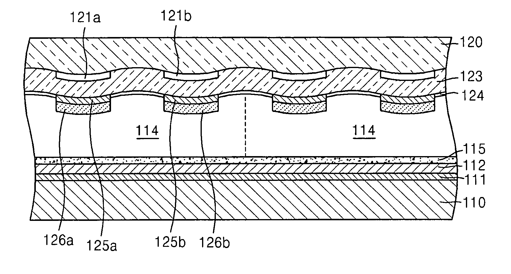
[0037]FIG. 3 is a partial cross-sectional view of a display device, e.g., a plasma display panel (PDP), according to an embodiment.

[0038] Referring to FIG. 3, an upper substrate 120, which is a first substrate, and a lower substrate 110, which is a second substrate, are spaced apart from each other with their surfaces facing each other. A plurality of discharge cells 114 where a plasma discharge occurs are formed between the upper substrate 120 and the lower substrate 110. Although not shown in FIG. 3, a plurality of barrier ribs, which divide a space between the upper substrate 120 and the lower substrate 110 to define the discharge cells 114 and prevent electrical and optical cross-talk between the discharge cells 114, are formed between the upper substrate 120 and the l...


PUM


Abstract

Provided is a display device comprising a first substrate and a second substrate facing each other with a plurality of discharge cells therebetween, a plurality of first electrodes formed on an inner surface of the first substrate, a plurality of curved electron emission sources disposed on the inner side of the first substrate to correspond to the first electrodes, a discharge gas filled in the discharge cells, and light emitting layers formed on inner walls of the discharge cells.

Description

CROSS-REFERENCE TO RELATED PATENT APPLICATIONS [0001] This application claims the benefit of Korean Patent Application No. 10-2005-0121940, filed on Dec. 12, 2005, in the Korean Intellectual Property Office, the disclosure of which is incorporated herein in its entirety by reference. BACKGROUND OF THE INVENTION [0002] 1. Field of the Invention [0003] The present embodiments relate to a display device, and more particularly, to a display device that can improve luminous efficiency and reduce a driving voltage. [0004] 2. Description of the Related Art [0005] Plasma display panels (PDPs) are display devices which display an image using an electrical discharge. PDPs have become popular due to their characteristics of high brightness and wide viewing angle. In PDPs, a gas discharge is generated between electrodes by voltages applied to the electrodes, and then visible light is emitted from a phosphor layer that is excited by ultraviolet (UV) rays created when the gas discharge is generat...

Claims


Application Information

Patent Timeline
Patent Type & Authority Applications(United States)
IPC IPC(8): H01J17/49H01J11/22H01J11/24H01J11/30H01J11/34H01J11/40
CPCH01J11/12H01J2211/24H01J2211/34H01J2211/38H01J2211/40C01B32/05H01J11/22H01J11/34H01J11/38
Inventor PARK, HYOUNG-BINSON, SEUNG-HYUNJANG, SANG-HUNKIM, GI-YOUNGKIM, SUNG-SOOLEE, SEONG-EUI
Owner SAMSUNG SDI CO LTD
Why Eureka
Try Eureka