Check patentability & draft patents in minutes with Patsnap Eureka AI!

Fuel cell-electrolyzer system controlled by a single bi-directional DC-to-DC converter

Active Publication Date: 2007-06-14
LOCKHEED MARTIN CORP
View PDF4 Cites 3 Cited by
  • Summary
  • Abstract
  • Description
  • Claims
  • Application Information

AI Technical Summary

Problems solved by technology

However, multiple DC-to-DC converters are redundant, add weight, cost and complexity to the system, and create an additional point of failure that could disable the system.

Method used


Image

  • Fuel cell-electrolyzer system controlled by a single bi-directional DC-to-DC converter
  • Fuel cell-electrolyzer system controlled by a single bi-directional DC-to-DC converter

Examples


first embodiment

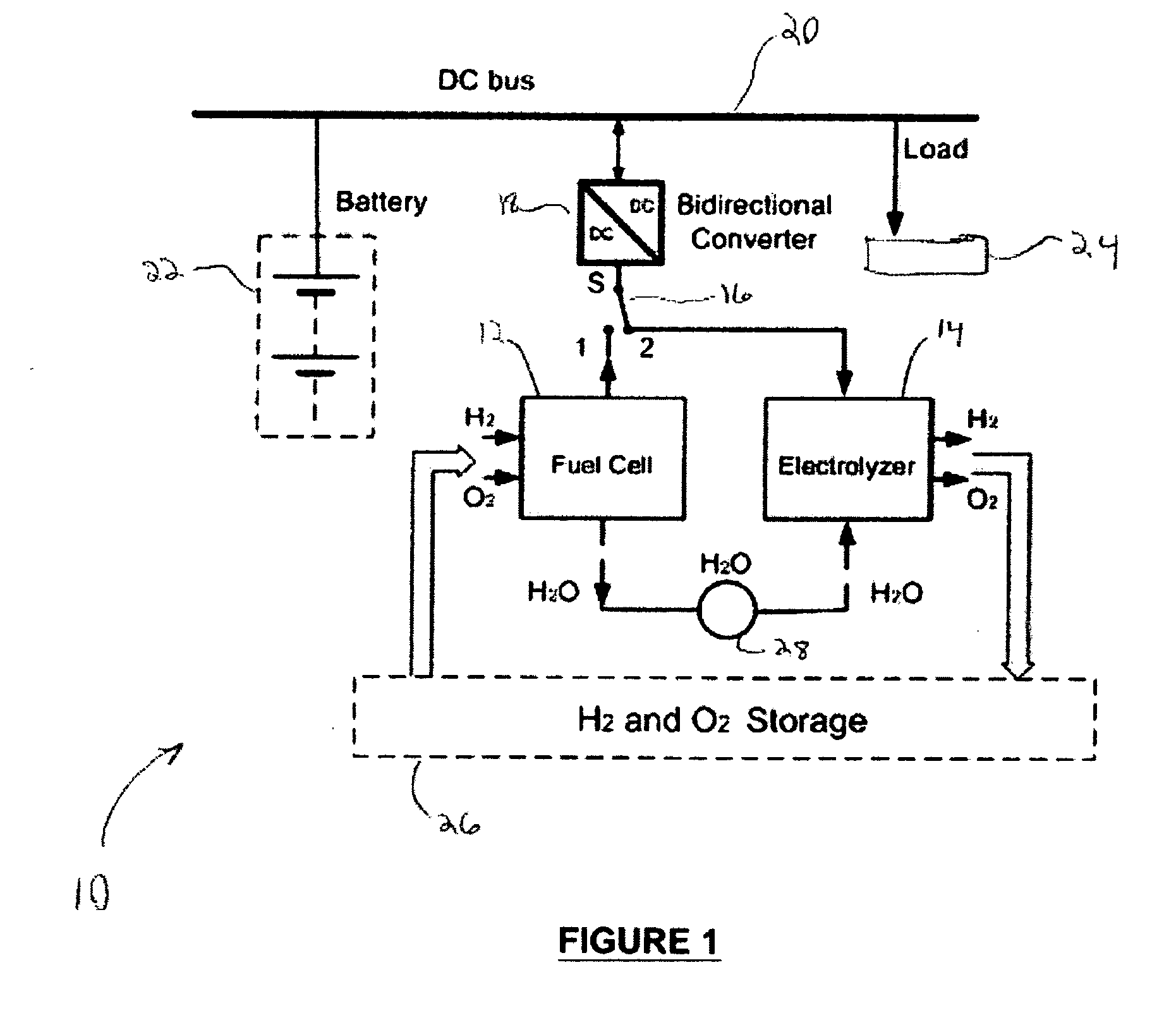
[0013] Referring now to FIG. 1, illustrated is a schematic representation of a closed-loop renewable hydrogen energy power system, generally 10, according to the present invention. In this embodiment, the power system 10 includes a separate fuel cell 12 and electrolyzer 14. A switch 16, which may include mechanical and / or electronic (e.g., solid state, etc.) selective power direction capability, selectively communicates one of the fuel cell 12 and electrolyzer 14 with a bi-directional DC-to-DC converter 18. The bi-directional DC-to-DC converter 18 also communicates with a DC bus 20 of the unit to be powered by the power system 10. Also connected to the DC bus 20 is an alternate power supply 22, illustrated in this exemplary embodiment as a battery, though this is merely representative and could be any other source of supply. Additionally, a load 24 to be powered by the power system 10 is connected to the DC bus 20.

[0014] When the fuel cell 12 is to supply energy to the DC bus 20, sw...

second embodiment

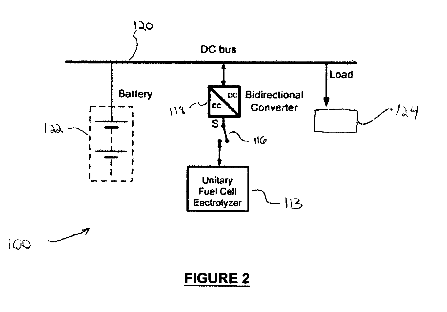
[0018] In this second embodiment, switch 116 connects or disconnects the unitary fuel cell electrolyzer 113 from the bi-directional DC-to-DC converter 118. Alternately, the function of the switch may be internalized with the unitary fuel cell electrolyzer 113 or the bi-directional DC-to-DC converter 118, or it may be eliminated altogether.

[0019] The closed-loop hydrogen energy system described herein is particularly applicable, by way of example only, to a continuously operative system that has an intermittent energy source in excess of its operating needs. Consider a continuously operating outdoor system powered by solar energy, preferably a mobile system (e.g., aircraft, land vehicle, watercraft, spacecraft, etc.). During the hours of daylight, the system receives solar energy and converts that energy to electricity, represented as source 22, 122, in excess of its operating needs. The excess electric energy is stored as chemical energy by electrolyzer 14, 113. During the hours of ...


PUM


Abstract

A self-contained regenerative power system includes a fuel cell operative to generate electric energy from hydrogen and oxygen, generating water as a byproduct, and an electrolyzer operative to generate hydrogen and oxygen from water by consumption of electric energy. A bi-directional DC-to-DC converter interfaces between the fuel cell and the electrolyzer on one side and the system to be powered on the other. A switch selectively connects either the fuel cell or the electrolyzer with the bi-directional DC-to-DC converter. The products of the fuel cell process can be supplied to the electrolyzer process, and vice versa. Alternately, the self-contained regenerative power system comprises a unitary fuel cell and electrolyzer.

Description

BACKGROUND OF THE INVENTION [0001] 1. Field of Invention [0002] The present invention relates to the field of alternative power sources, and more particularly to a power control device and method in a closed-loop renewable hydrogen energy system. [0003] 2. Description of Related Art [0004] A closed-loop renewable hydrogen energy system is generally comprised of two core components. A fuel cell combines constituent hydrogen and oxygen to produce water (H2O) and generates electricity from the energy released by the reaction. On the other hand, an electrolyzer consumes electrical energy to and stores it as chemical energy by dividing water into its constituent elements, hydrogen and oxygen. To complete the closed loop, the water produced by the fuel cell is the input material for the electrolyzer, and the hydrogen and oxygen produced by the electrolyzer are the input materials for the fuel cell. [0005] According to the prior art, the electrolyzer and fuel cell are each separately inter...

Claims


Application Information

Patent Timeline
IPC IPC(8): H01M10/44
CPCH01M16/003Y10S136/291Y10S323/906Y02E60/50
Inventor GJINI, ORGESDAME, MARKKROK, MICHAEL
Owner LOCKHEED MARTIN CORP
Features
  • R&D
  • Intellectual Property
  • Life Sciences
  • Materials
  • Tech Scout
  • Unparalleled Data Quality
  • Higher Quality Content
  • 60% Fewer Hallucinations
Learn More