Input device, input method and application of electronic cipher code lock
- Summary
- Abstract
- Description
- Claims
- Application Information
AI Technical Summary
Benefits of technology
Problems solved by technology
Method used
Image
Examples
first embodiment
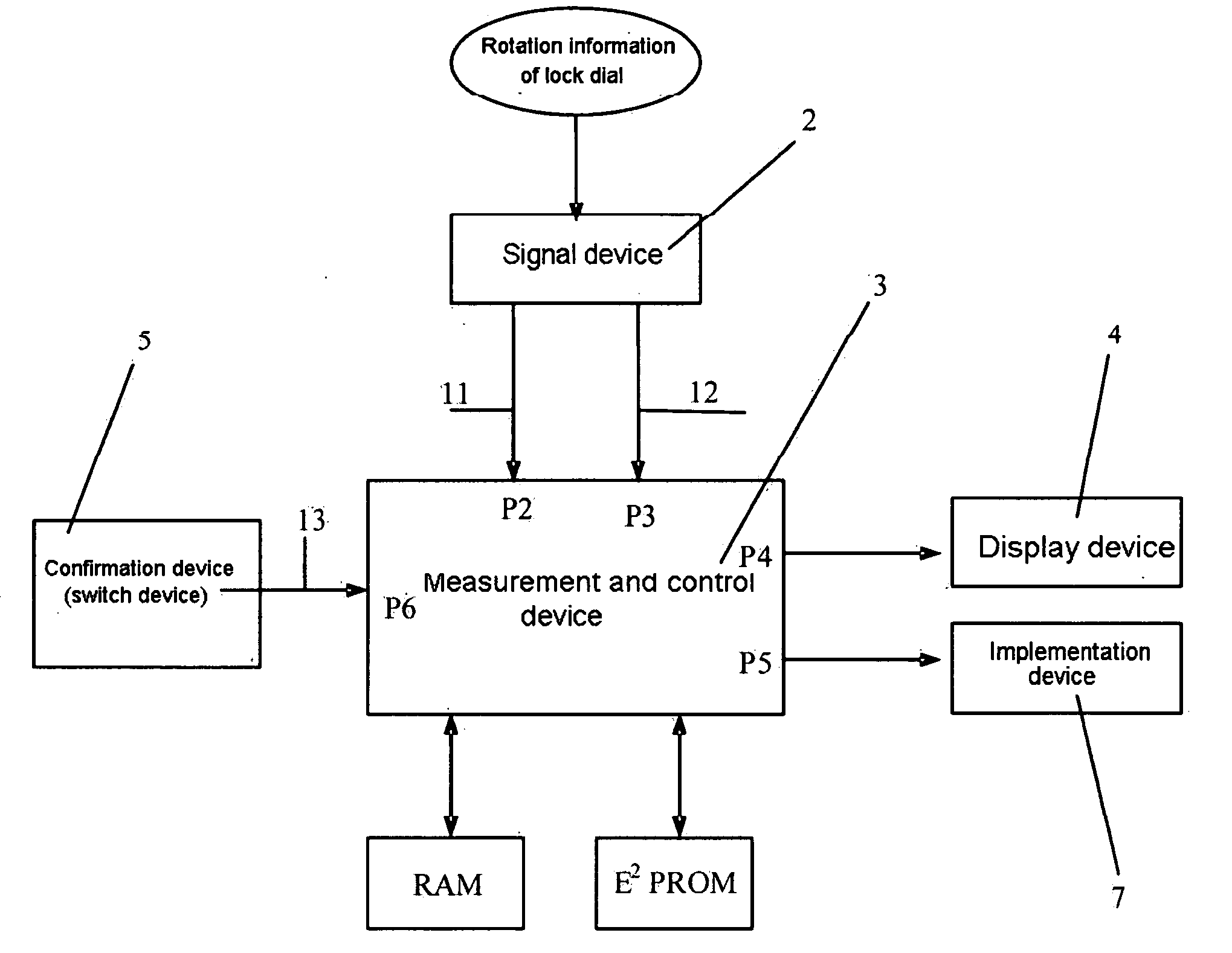
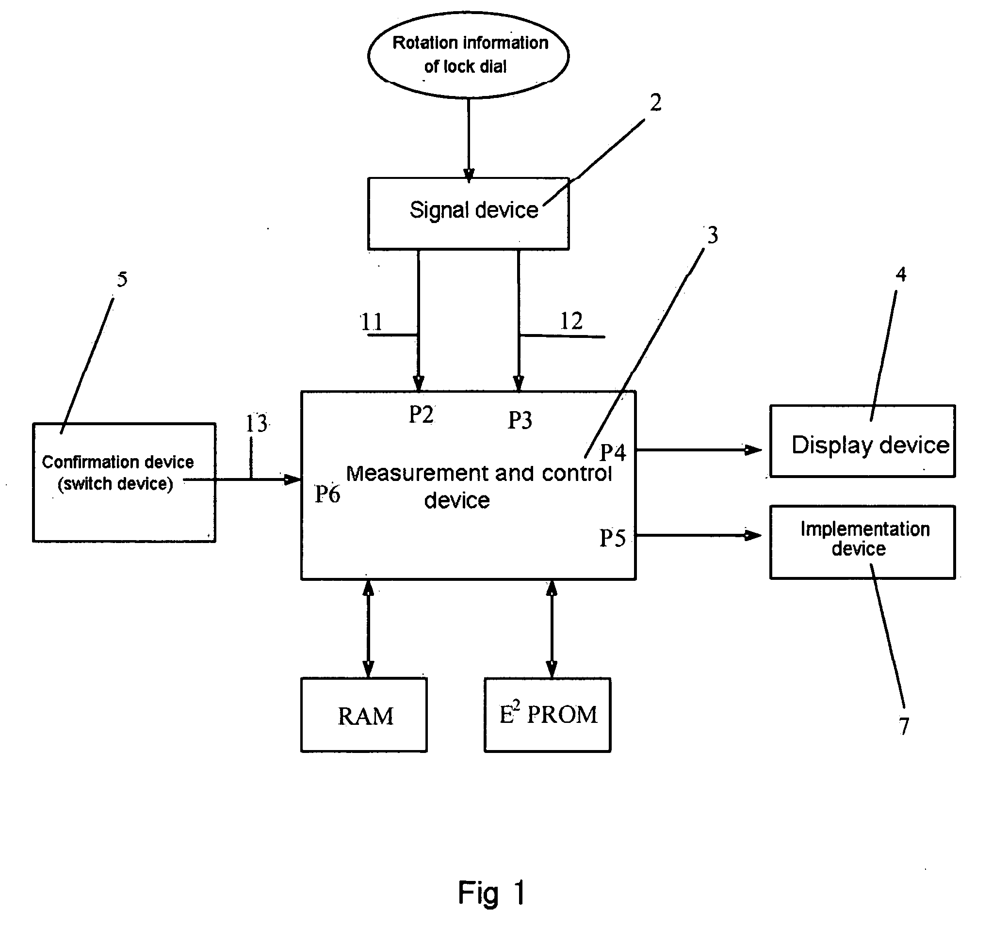
[0053]FIG. 1 shows an input device of the electronic cipher code lock according to the invention. As shown in the drawing, said input device of the electronic cipher code lock is composed of a signal device 2, a measurement and control device 3, a display device 4 and a confirmation device 5.
[0054] The signal device 2 can employ an electromechanical rotation coder, the rotor of the coder has a mechanical driving relationship with the dial and rotates following the dial. The coder has two code signal output terminals, when the dial rotates in a clockwise direction, the electrical pulse signal 11 outputted from the first output terminal keeps ahead; when the dial rotates in a counterclockwise direction, the electrical pulse signal 12 outputted from the second output terminal keeps ahead. The number of the pulses included in the two groups of electrical pulse signals is proportional to the angle through which the rotor of the coder has rotated, and the frequency of the pulse signals is...
second embodiment
[0070]FIG. 5 shows a structure of the dial in the invention. As shown in the drawing, the internal edge of the dial 101 has a circular skirt-like fringe 123, said skirt-like fringe corresponds to a position between the transmitter tube and the receiver tube of the photoelectric switch 107 on the circuit board 109. When the dial 101 is depressed, the light signal of the photoelectric switch 107 is blocked by the skirt-like fringe 123, causing the electrical signal outputted from the photoelectric switch 107 to change, and the electrical signal is transmitted to MCU 106, when the change of the signal is detected by MCU 106, the number displayed currently is confirmed and stored as a part of the cipher code. After releasing the external force for depressing the dial 101, the dial 101 and drive shaft 102 are reset under the reset function of the reset spring 104.
[0071] The shape of driving gears 103 is shown in FIG. 4, a simple mechanism is constituted by a concentric circle plane gulle...
PUM
 Abstract
Description
Claims
Application Information
 - R&D
- Intellectual Property
- Life Sciences
- Materials
- Tech Scout
- Unparalleled Data Quality
- Higher Quality Content
- 60% Fewer Hallucinations
Browse by: Latest US Patents, China's latest patents, Technical Efficacy Thesaurus, Application Domain, Technology Topic, Popular Technical Reports.
© 2025 PatSnap. All rights reserved.Legal|Privacy policy|Modern Slavery Act Transparency Statement|Sitemap|About US| Contact US: help@patsnap.com


