Fuel cell system and water recovery method thereof

Inactive Publication Date: 2007-06-14
NISSAN MOTOR CO LTD
View PDF7 Cites 18 Cited by
  • Summary
  • Abstract
  • Description
  • Claims
  • Application Information

AI Technical Summary

Benefits of technology

[0005] It is therefore an object of this invention to prevent water recovered from the exhaust gas of a fuel

Problems solved by technology

In the prior art described above, however, when the fuel cell system is started up below freezing point, the water may conden

Method used


Image

  • Fuel cell system and water recovery method thereof
  • Fuel cell system and water recovery method thereof
  • Fuel cell system and water recovery method thereof

Examples


first embodiment

[0053] Focussing mainly on the differences with the first embodiment, the fuel cell system shown in FIG. 4 is a fuel reforming fuel cell system which generates hydrogen by reforming methanol, which is an alcohol fuel, using a fuel reforming device 91, and supplies the generated hydrogen to the fuel cell stack 5.

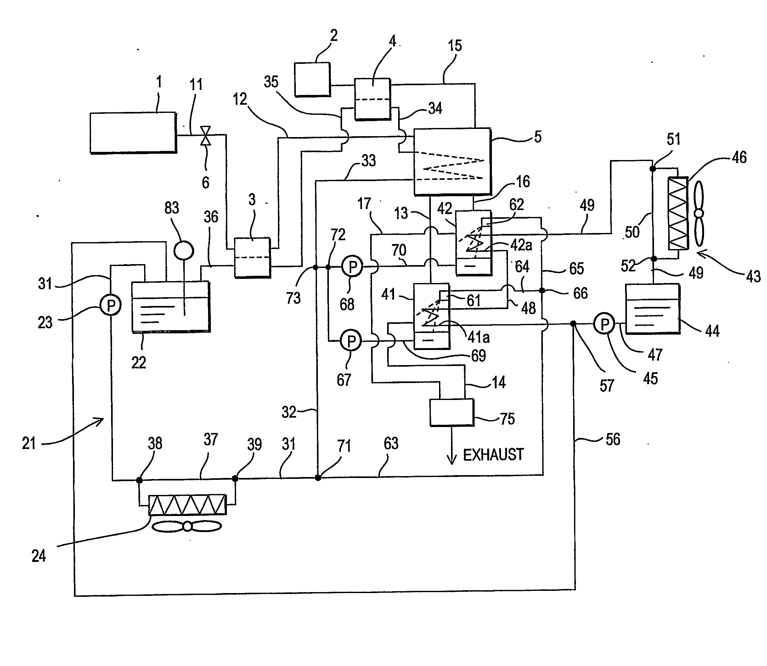
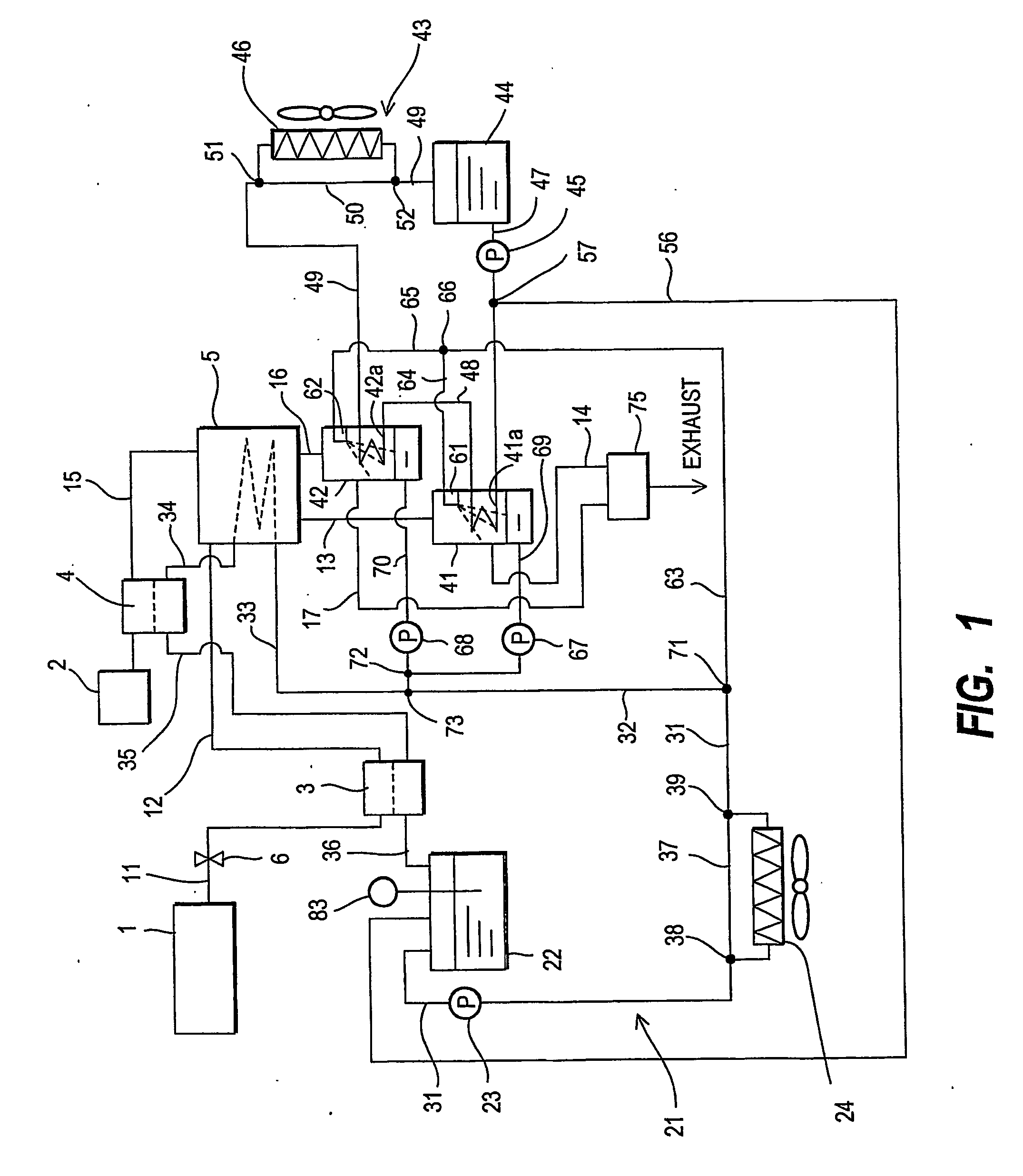
[0054] The reforming fuel cell system will now be described. A device which supplies methanol and water to the fuel reforming device 91 is constituted by a methanol tank 92, a pump 93, a liquid mixture tank 95, and a pump 96. The methanol and water, which serve as the raw materials of the reformate gas, are pumped from the liquid mixture tank 95 by the pump 96 and supplied to the fuel reforming device 91 through a passage 97. The air that is used in the reforming process is supplied from a blower 98 to the fuel reforming device 91 through a passage 99. The hydrogen (reformate gas) generated in the fuel reforming device 91 is supplied to the fuel cell stack 5 together with air...

second embodiment

[0058] The condensed water mixed with the methanol is a water-compatible solution, and accordingly, the melting point of this solution falls below zero degrees centigrade, which is the melting point of pure water. Hence in the second embodiment also, condensed water can be prevented from freezing below freezing point.

[0059] The control valve 72 is provided at the convergence portion of the two passages 69, 70 opening from the bottom of the condensers 41, 42. By controlling the control valve 72 as the pumps 67, 68 are operated, the water recovered by the condensers 41, 42 is returned to the liquid mixture tank 95 through a passage 103.

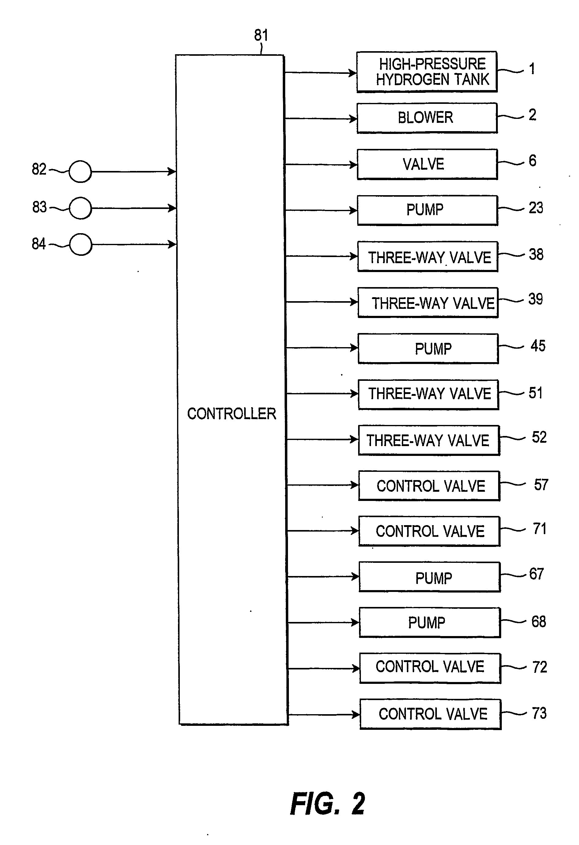
[0060] As shown in FIG. 5, the ambient temperature Th of the condensers 41, 42, which is detected by the ambient temperature sensor 82, and the methanol concentration of the liquid mixture in the liquid mixture tank 95, which is detected by a methanol concentration sensor 85, are input into the controller 81 together with a load condition of the movabl...


PUM


Abstract

A fuel cell system comprises a fuel gas supply mechanism (1, 91-97) which supplies a fuel gas, an oxidizing gas supply mechanism (2) which supplies an oxidizing gas, a fuel cell (5) which generates power using the fuel gas supplied from the fuel gas supply mechanism (1, 91-97) and the oxidizing gas supplied from the oxidizing gas supply mechanism (2), and a water recovery device (41, 42) which separates and recovers water contained in exhaust gas from the fuel cell (5), and mixes the recovered water with a water-compatible liquid in the location where the water is separated and recovered.

Description

TECHNICAL FIELD OF THE INVENTION [0001] This invention relates to a fuel cell which generates power using fuel gas and oxidizing gas, and more particularly to preventing water inside a fuel cell from freezing in low temperature environments. BACKGROUND OF THE INVENTION [0002] In a fuel cell system for use in a movable body, in contrast to a stationary fuel cell system, there are times when it is impossible to replenish the water that is required in the system, and hence a system which recovers the water contained in the exhaust gas of the fuel cell stack is required. In a fuel cell system disclosed in JP8-91804A, published by the Japan Patent Office in 1996, a water separator is provided for recovering water contained in the gas that is discharged from a fuel cell stack. SUMMARY OF THE INVENTION [0003] In a fuel cell system for a movable body, water must be recovered from the exhaust gas of the fuel cell stack by a water recovery device even when the movable body is located in a sub...

Claims


Application Information

Patent Timeline
IPC IPC(8): H01M8/04H01M8/00H01M8/06H01M8/10
CPCH01M8/04007H01M8/04029H01M8/04119H01M8/04134H01M8/04141H01M8/04156H01M8/04164H01M8/04253H01M8/0612H01M8/1002H01M2250/20Y02E60/521Y02T90/32H01M8/1007Y02T90/40Y02E60/50
Inventor NUMAO, YASUHIROIWASAKI, YASUKAZUABE, MITSUTAKA
Owner NISSAN MOTOR CO LTD
Why Eureka
Try Eureka