

Dry-cleaning machine
- Summary
- Abstract
- Description
- Claims
- Application Information
AI Technical Summary
Benefits of technology
Problems solved by technology
Method used
Image

Examples
first embodiment
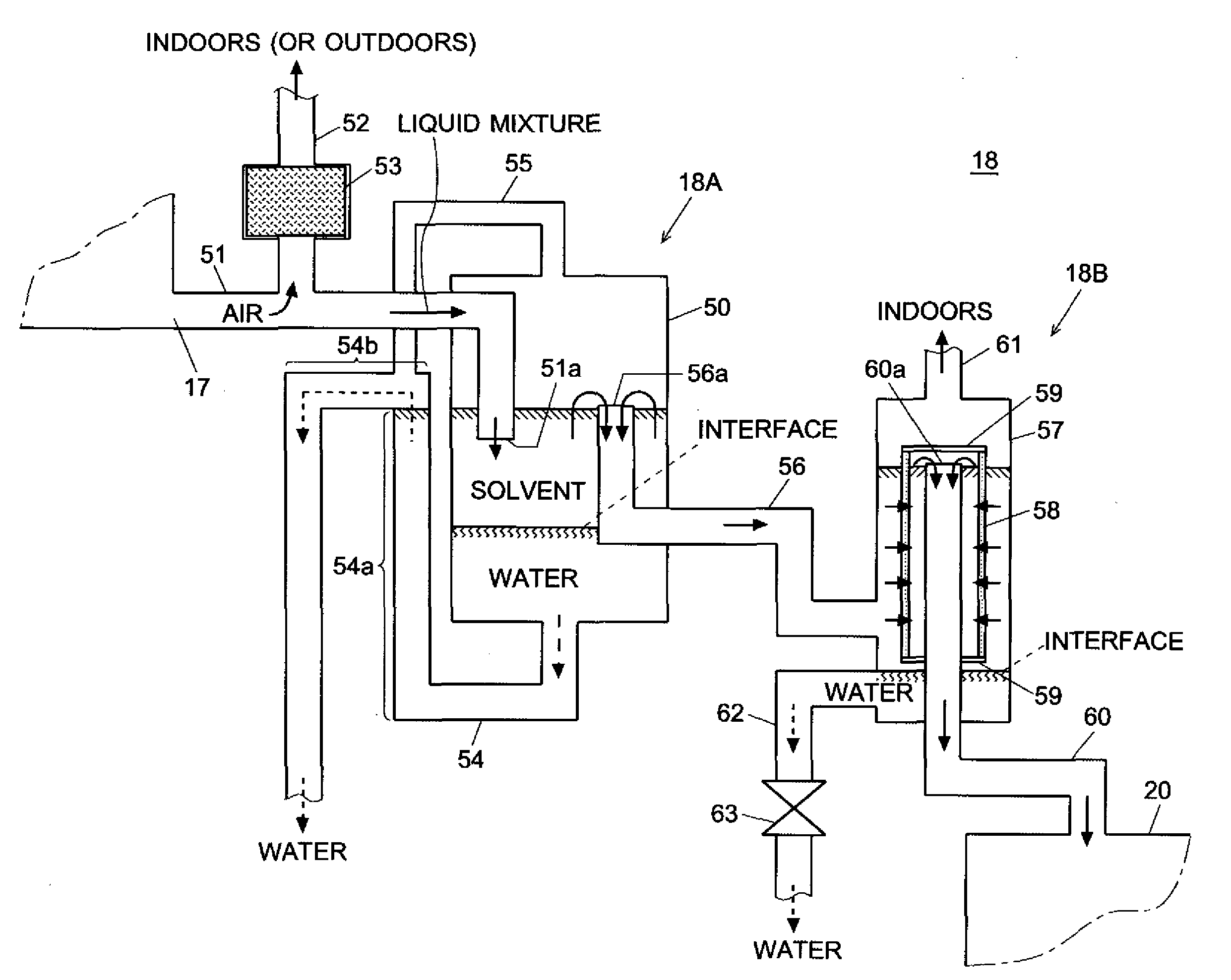
[0127]The dry-cleaning machine is characterized by the water separator 18 for separating and removing water from the solvent condensed during the drying and recovering operation or drying and exhausting operation. The following description focuses on the detailed construction and operation of the water separator 18, referring to FIG. 4.
[0128]FIG. 4 is a vertical sectional view of the water separator 18 used in the present embodiment. In FIG. 4, the components that are functionally equivalent to those of the water separator previously described in FIG. 7 are indicated by the same numerals; explanation of those components will be omitted unless it is especially necessary. The liquid storage tank 50 in FIG. 7 is called the “first” liquid storage tank 50 in FIG. 4 to distinguish it from another liquid storage tank. This remark also applies to the drainage pipes.
[0129]In this water separator 18, an air relief pipe 52 having an activated carbon filter 53 is connected to an intermediate p...
second embodiment
[0141]FIG. 5 is a vertical sectional view of the water separator 18 in the In FIG. 5, the components that are functionally equivalent to those of the water separators previously described in FIGS. 4 and 7 are indicated by the same numerals.
[0142]In this water separator 18, an air relief pipe 52 having an activated carbon filter 53 is connected to an intermediate point of the liquid mixture line 51, which guides the liquid mixture from the drainage port 17 to the liquid storage tank 70. The activated carbon filter 53 catches the vaporized solvent contained in the air exhausted through the air relief pipe 52. The activated carbon filter 53 may be omitted if a small amount of leakage of the vaporized solvent is allowable, for example if the air relief pipe 52 is extended so that its outlet is located outdoors and the air is exhausted outdoors directly.
[0143]The outlet end 51a of the liquid mixture line 51 is not connected to the wall of the liquid storage tank 70; it is further extend...
PUM
 Abstract
Description
Claims
Application Information