Controlling for monitoring and controlling pulsators in a milking system

Active Publication Date: 2007-06-21
TECH HLDG
View PDF2 Cites 26 Cited by
  • Summary
  • Abstract
  • Description
  • Claims
  • Application Information

AI Technical Summary

Benefits of technology

[0038] Therefore, it is an advantage of the present invention to provide apparatus, a system and method for monitoring and controlling operating pulsators in a milking system.
[0039] Another advantage of the present invention is that a microprocessor in the pulsator controller generates at least one control signal when the monitored pulsator pulsating vacuum level is at a vacuum level outside of a programmed predetermined vacuum range.
[0040] Another advantage of the present invention is that the pulsator controller has a control circuit for signaling that a monitored pulsator pulsating vacuum level is outside of the range of pulsating vacuum levels programmed as acceptable for the milking system pulsators.
[0041] Another advantage of the present invention is that the pulsator controller control circuit is capable of disabling operation of the monitored pulsator havi

Problems solved by technology

Improper or defective operation of a pulsator or a malfunction of a pulsator, if allowed to go unnoticed for a considerable period of time, can cause damage to the cow.
Such damage results because of trauma experienced by the teat of a dairy animal arising from improper teat cup liner movement and such damage could include causing mastitis to the dairy animal.
If the infection is severe enough, significant and sometimes permanent damage can be caused to the cow's normal milk producing organisms.
All mastitis cause some level of permanent and lifetime irrefutable damage to the animal's milk producing (mammary) system.
As such, a severe or lengthy period of infection may limit the animal's production capabilities and affect the animal's milk producing life.
First, mastitis is caused by application of damaging vacuum levels to the cows' teats which create a severe irritation.
Since it is difficult to isolate with any degree of certainty at what level of vacuum such irritation occurs, the conservative approach is the least level of vacuum, the

Method used


Image

  • Controlling for monitoring and controlling pulsators in a milking system
  • Controlling for monitoring and controlling pulsators in a milking system
  • Controlling for monitoring and controlling pulsators in a milking system

Examples


Example

[0071] Before proceeding with the description of the preferred embodiment, the following background will be helpful in understanding this invention.

Description of Milking System

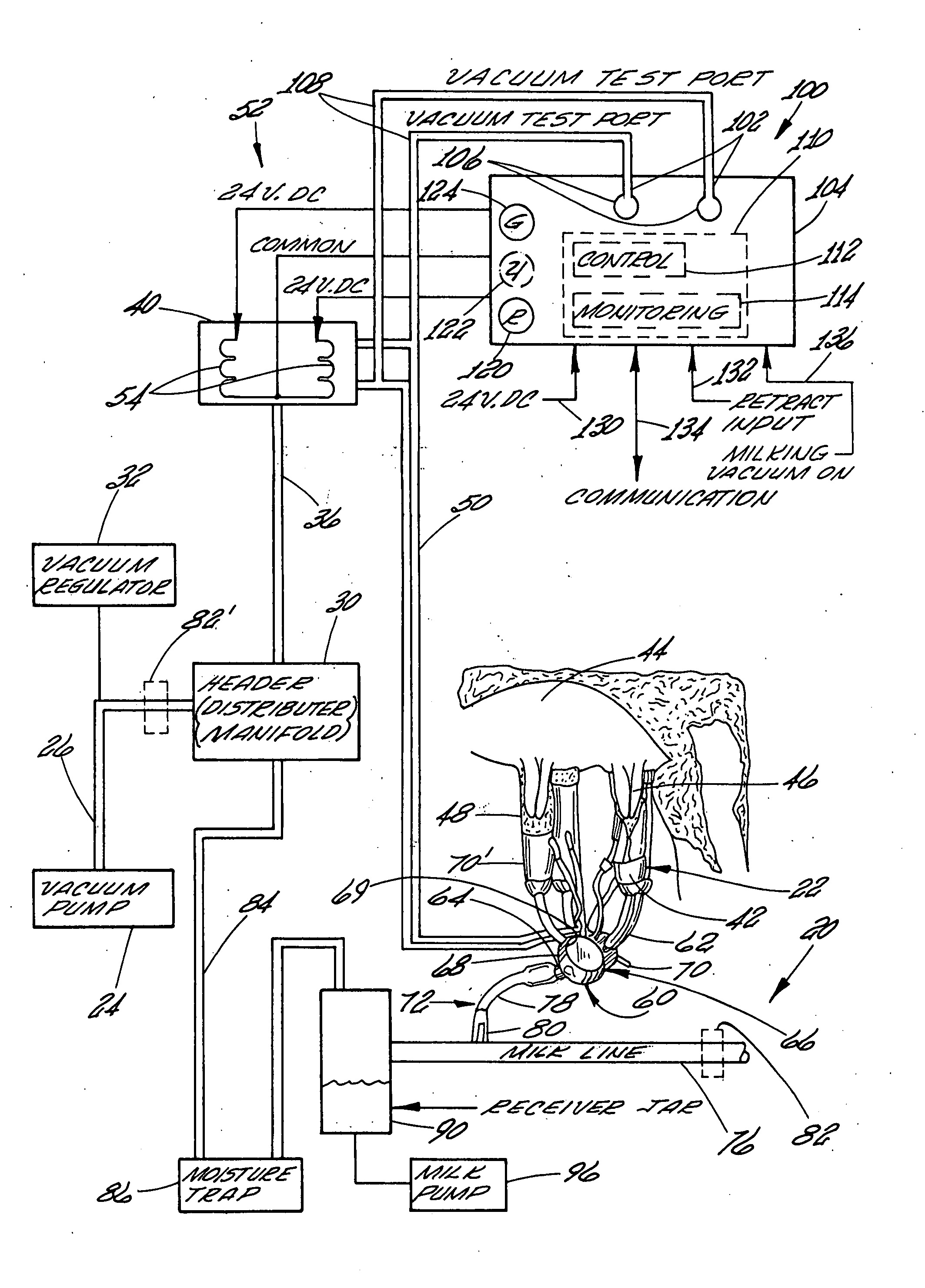
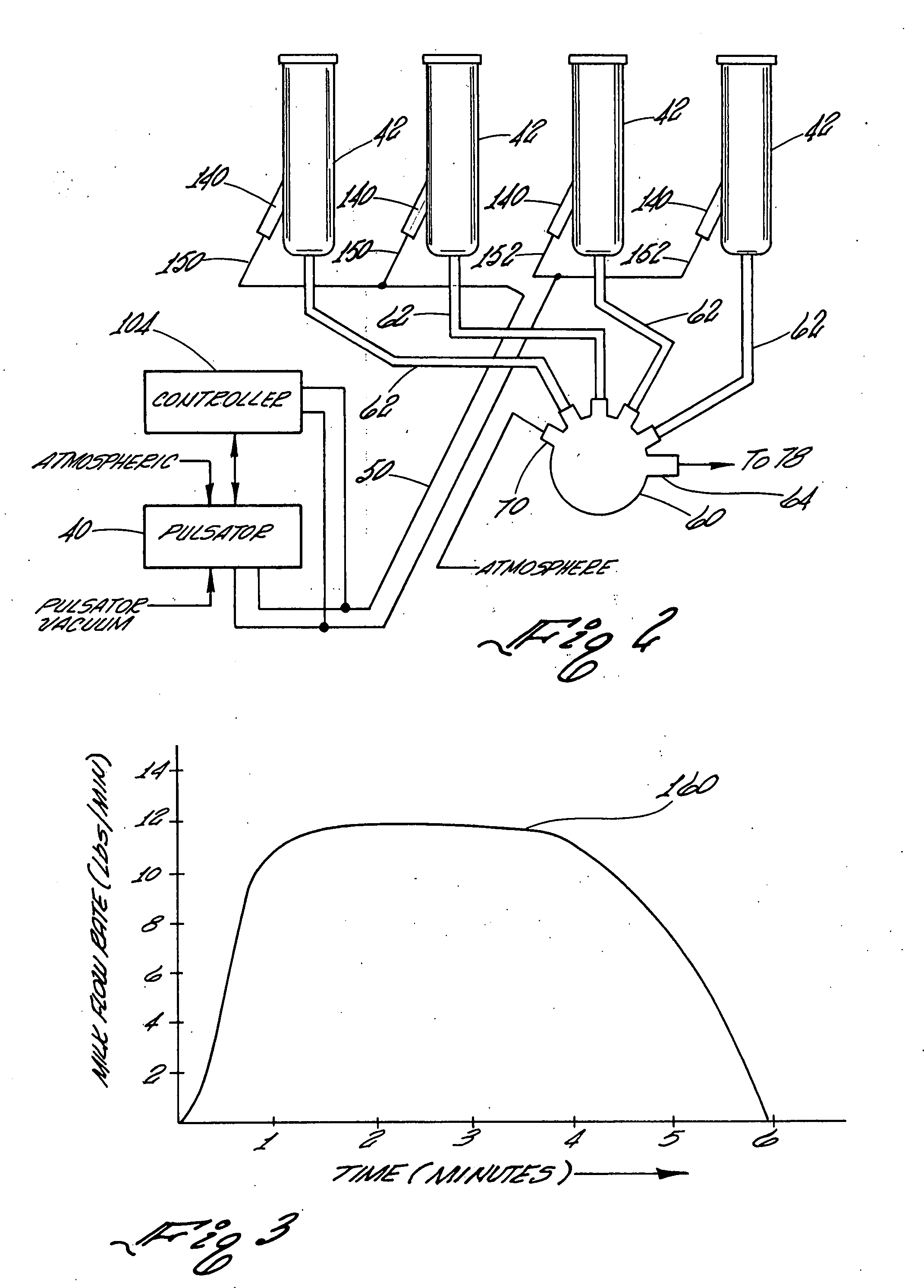
[0072] When a cow enters a milking barn or milking parlor, such as a herring bone style milking parlor, and the milking machine or milking apparatus is connected to the animal's body and a milking vacuum is applied to the apparatus, the body starts to react in preparation for “letting down” of the diary animal's, e.g. cow's, milk. A natural process takes place wherein the animal produces within the animal's blood stream a chemical called “oxitosin”. This chemical works its way down into the udder causing the ovili cells to contract. In essence, contraction of the ovili cells causes a squeezing effect to help push out, expel or withdraw the animal's milk. The period of time the animal produces this oxitosin is limited, and recent research suggests somewhere between 4 minutes and 6 minutes on average.

[0073] ...


PUM


Abstract

A controller for monitoring and controlling an operating pulsator in a milking system is shown. The controller receives a start signal generated when a milking apparatus is attached to a cow. A first sensor is operatively connected to a designated pulsator for receiving a pulsating vacuum and for producing a first signal representing the pulsating vacuum level. The controller includes a processor having a comparator for comparing the first signal to a stored reference of predetermined vacuum ranges and for generating a control signal when the designed pulsator pulsating vacuum level is outside of a predetermined vacuum range. A control circuit signals that the designated pulsator pulsating vacuum level is outside of the predetermined vacuum range.

Description

CROSS-REFERENCES TO RELATED APPLICATIONS [0001] This Application is a Continuation-in Part of U.S. patent application Ser. No. 11 / 248,958 filed Oct. 12, 2005 which is a Continuation of U.S. patent application Ser. No. 10 / 359,834 filed Feb. 7, 2003 and which has issued as U.S. Pat. No. 6,990,924.STATEMENT REGARDING FEDERALLY SPONSORED RESEARCH OR DEVELOPMENT [0002] Not Applicable REFERENCE TO A “MICROFICHE APPENDIX” (SEE 37 CFR 1.96) [0003] Not Applicable BACKGROUND OF THE INVENTION [0004] 1. Field of the Invention [0005] The present invention relates to apparatus, method and system of supervising, monitoring and controlling all of the pulsators of a milking machine having a teat cup with a teatcup liner and a pulsation chamber comprising applying a milking vacuum to the interior of the teatcup liner and a pulsating vacuum to the pulsation chamber so that the teat cup liner cyclically moves between a substantially open position and a substantially closed position under control of pul...

Claims


Application Information

Patent Timeline
IPC IPC(8): A01J5/007
CPCA01J5/007A01J5/14
Inventor BROWN, STAN A.FEMATT, RAFAEL ANTONIO
Owner TECH HLDG
Why Eureka
Try Eureka