Internal combustion engine

a technology of internal combustion engine and piston, which is applied in the direction of machines/engines, mechanical devices, cylinders, etc., can solve the problems of difficulty in achieving sufficient bearing strength

Active Publication Date: 2007-06-21
NISSAN MOTOR CO LTD
View PDF2 Cites 20 Cited by
  • Summary
  • Abstract
  • Description
  • Claims
  • Application Information

AI Technical Summary

Benefits of technology

[0007] One object of the invention to improve upon the above mentioned conventional technology. Other objec

Problems solved by technology

In this type of multilink-type piston-crank, when the piston-stroke characteristics change, an excessive force acts on specific crankshaft bearings a

Method used


Image

  • Internal combustion engine
  • Internal combustion engine
  • Internal combustion engine

Examples


fourth embodiment

[0061]FIG. 5 illustrates the present invention, and is a sectional view of the first, third, and fifth crankshaft bearings 11a, 11c and 11e included in the multilink-type internal combustion engine. Components shown in FIG. 5 that are the same as those in FIG. 13 are given the same reference numerals, but FIG. 5 is different from FIG. 13 in that the side surfaces of the bulkheads 26 of the crankshaft bearings 11a, 11c and 11e in the front-back direction of the engine are partially depressed to form recesses 25. Each of the recesses 25 is provided at a position above the corresponding bearing surface 19. In order to attain a sufficient dimension in the front-back direction of the engine for each bearing surface 19, each recess 25 is disposed above the crankshaft bearing surface 19 by a predetermined distance ΔS and is provided in a fan-shaped region about the crankshaft bearing surface 19.

[0062] In the fourth embodiment, the bulkheads 26 of the highly-rigid bearings 11b and 11d have ...

first embodiment

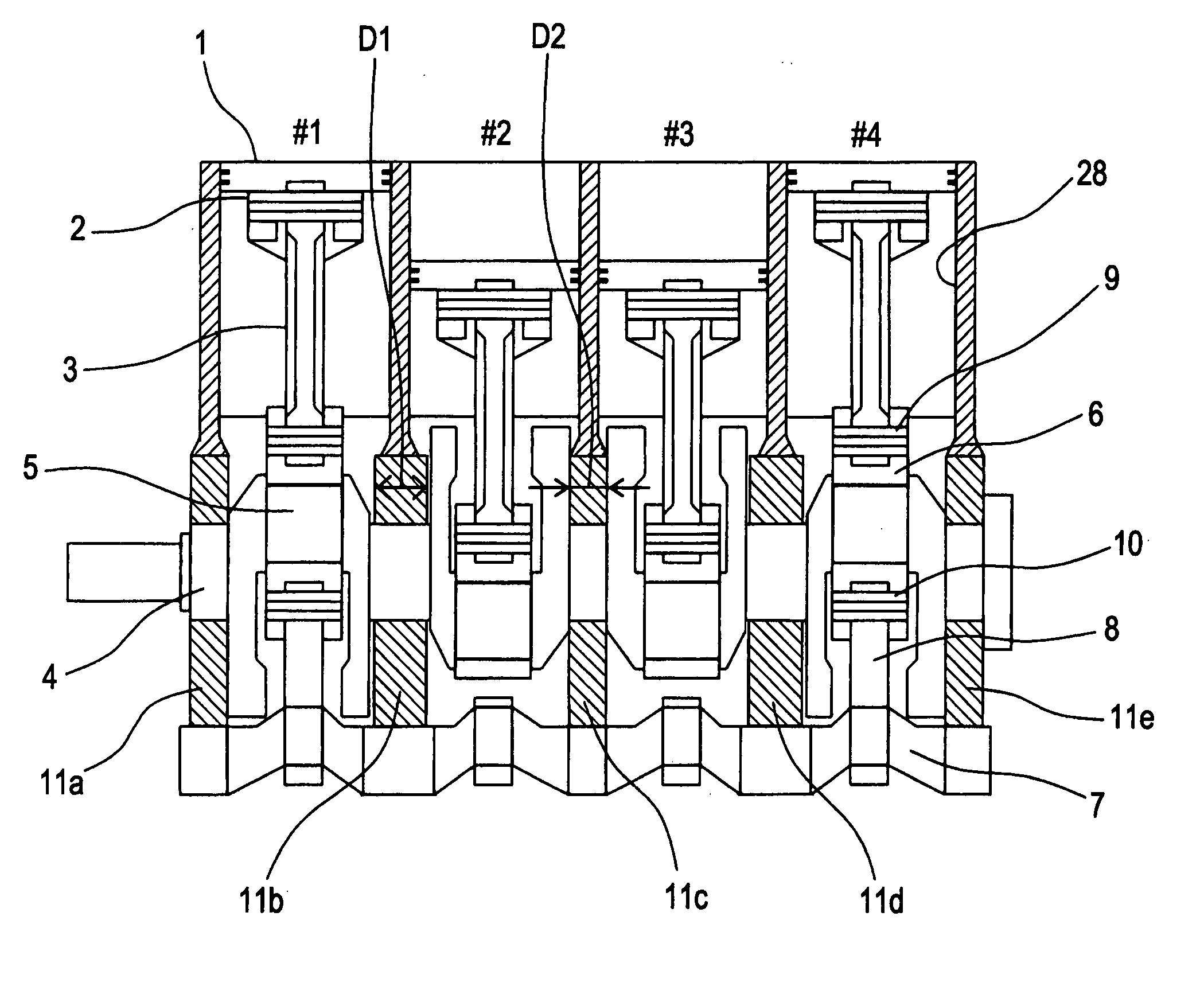
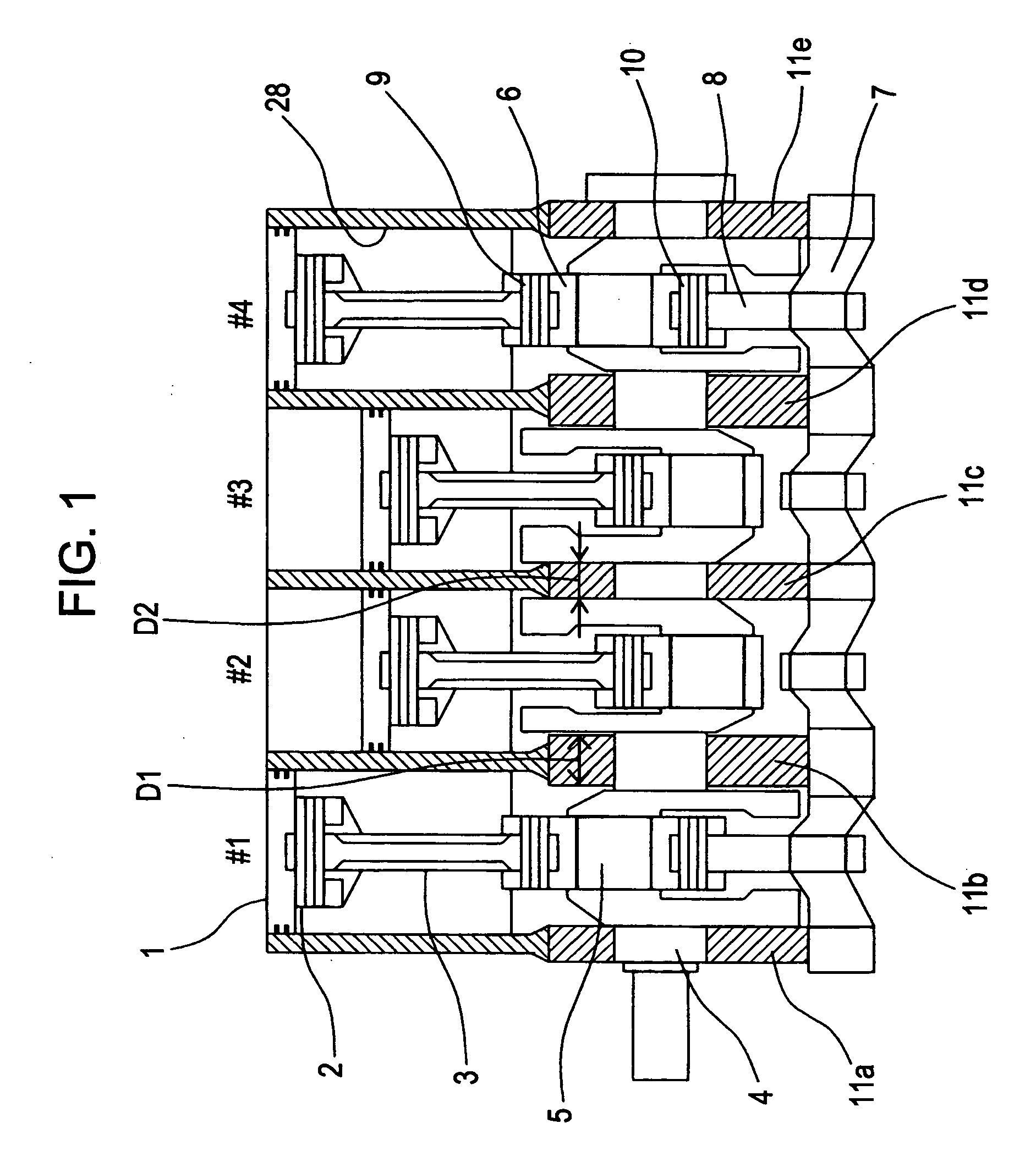
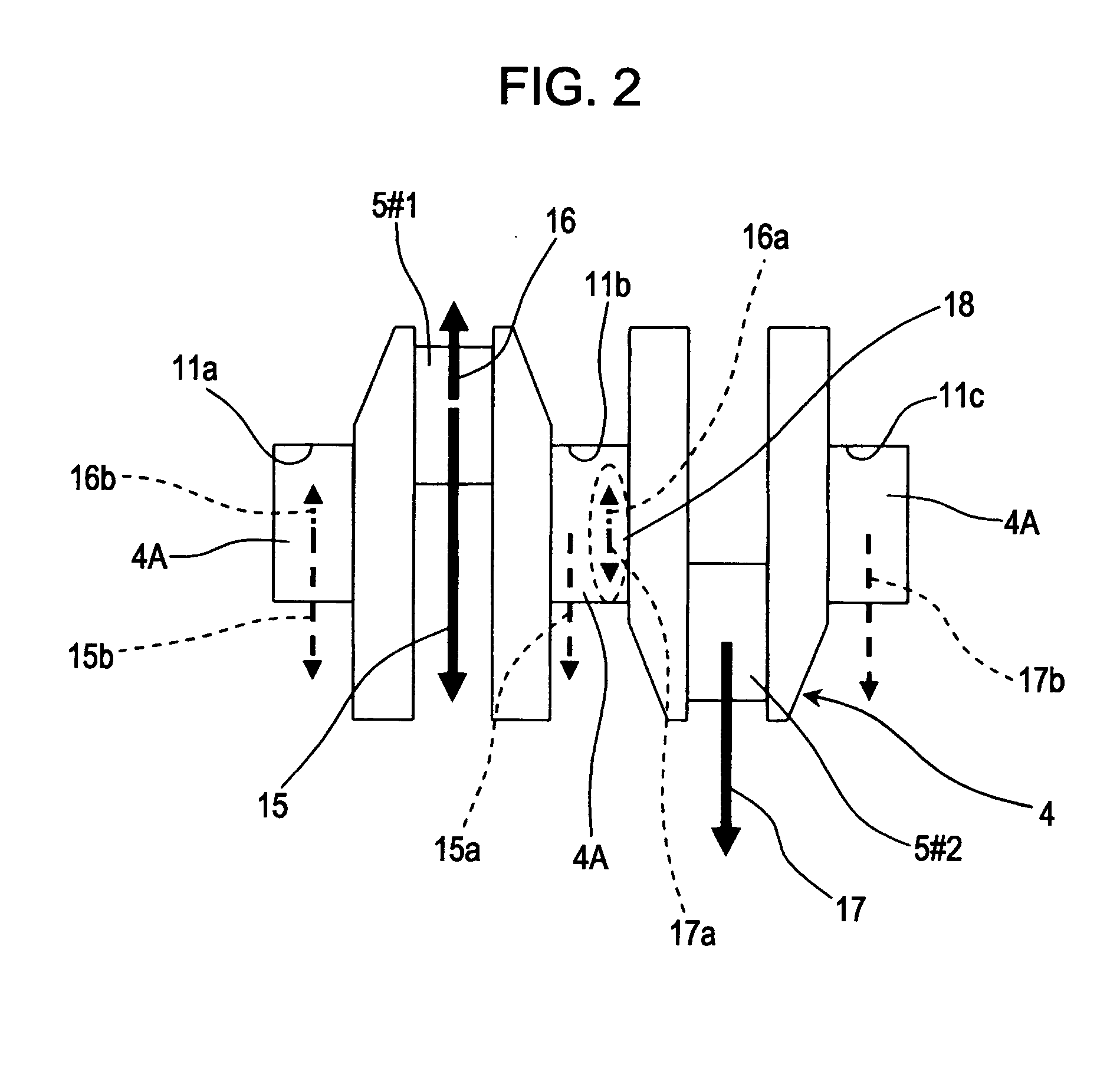
[0078] In the first embodiment shown in FIGS. 1 and 2, the dimension D2 in the front-back direction of the engine for the third, first, or fifth crankshaft bearings 11c, 11a, or 11e from the front of the internal combustion engine is smaller than the dimension D1 in the front-back direction of the engine for the second crankshaft bearing 11b and the fourth crankshaft bearing 11d so that the rigidity of the third, first, or fifth crankshaft bearings 11c, 11a, or 11e is lower than that of the second and fourth crankshaft bearings 11b and 11d. Thus, the aforementioned force-reducing effect is achieved. In this case, the third, first, or fifth crankshaft bearings 11c, 11a, or 11e, that receive less force than the second and fourth crankshaft bearings 11b and 11d, are reduced in width, such that the dimension of the engine in the front-back direction can be reduced.

[0079] In the second to fourth embodiments shown in FIGS. 3 to 5, the second and fourth crankshaft bearings 11b and 11d from...

second embodiment

[0082] In the second embodiment shown in FIG. 3, each of the highly-rigid bearings 11b and 11d has the housing 24 of the variable-compression-ratio actuator 31 fastened thereto in order to increase the rigidity of the highly-rigid bearings 11b and 11d. More specifically, a plurality of film-like bulkheads 26 integrally provided in the cylinder block 12 and the ladder frame 13 fixed to the lower surfaces of the bulkheads 26 are provided. The ladder frame 13 is provided with a plurality of first bearing caps 27 that rotatably support the journals 4A of the crankshaft 4 together with the bulkheads 26. Moreover, there are also provided second bearing caps 14 which are fixed to the lower surface of the ladder frame 13 and rotatably support the control shaft 7 together with the ladder frame 13. Furthermore, the second bearing caps 14a that are positioned below the highly-rigid bearings 11b and 11d each have the housing 24 of the variable-compression-ratio actuator 31 fixed thereto. Conseq...


PUM


Abstract

A piston-crank mechanism links crankpins of a crankshaft with piston pins of pistons by using a plurality of links. The piston-crank mechanism allows an upward inertia force produced near a top dead center of each piston to be smaller than a downward inertia force produced near a bottom dead center of the piston in order to reduce secondary vibration occurring during operation. In a four-cycle inline four-cylinder internal combustion engine, a total force of inertia forces exerted from adjacent cylinders to each of second and fourth crankshaft bearings becomes a downward force, which reinforces a downward force produced in response to combustion pressure. These second and fourth crankshaft bearings have a rigidity higher than the remaining crankshaft bearings.

Description

CROSS-REFERENCE TO RELATED APPLICATIONS [0001] This application claims priority from Japanese Patent Application Serial No. 2005-362587, filed 16 Dec. 2005, the entire contents of which are expressly incorporated herein by reference. BACKGROUND OF THE INVENTION [0002] 1. Field of the Invention [0003] The present invention generally relates to multi-cylinder internal combustion engines having a plurality of cylinders arranged in an array. In particular, the present invention relates to an improved crankshaft bearing structure suitable for an internal combustion engine equipped with a multilink-type piston-crank mechanism. [0004] 2. Background Information [0005] Most internal combustion engines used in vehicles have a plurality of cylinders with a piston reciprocating in each of the cylinder and a crankshaft that is linked to the pistons by a piston-crank linking mechanism. Some internal combustion engines use a multilink-type piston-crank mechanism in which upper links are connected ...

Claims


Application Information

Patent Timeline
IPC IPC(8): F02F7/00F02B75/32F16C11/00
CPCF02B75/048Y10T74/2174F02B75/32
Inventor TAKAHASHI, NAOKITANAKA, YOSHIAKIMIZUNO, HIDEAKIUSHIJIMA, KENSHINUNOME, YOSHIMI
Owner NISSAN MOTOR CO LTD
Why Eureka
Try Eureka