
Ignition apparatus for an internal combustion engine

a technology of internal combustion engine and ignition apparatus, which is applied in mechanical equipment, machines/engines, instruments, etc., can solve the problem of increasing the size of the circuit, and achieve the effect of preventing the increase of the circuit siz

Active Publication Date: 2007-06-21
MITSUBISHI ELECTRIC CORP
View PDF12 Cites 13 Cited by
  • Summary
  • Abstract
  • Description
  • Claims
  • Application Information

AI Technical Summary

Benefits of technology

[0006] It is an object of the present invention to provide an ignition apparatus for an internal combustion engine which allows an ignition signal and an ion current output signal to be transmitted through a single signal line and prevents erroneous ignition from being caused even if disturbances are added to those signals during transmission thereof.
[0008] In the ignition apparatus for the internal combustion engine according to the present invention, an ignition signal and an ion current output signal are transmitted through the single signal line, and there is set a difference between a voltage resulting from the ignition signal and a voltage resulting from the ion current output signal such that the switching element for generating a high voltage for ignition in the ignition plug is held OFF when the ion current output signal is transmitted. Thus, the ignition apparatus achieves an effect of preventing the size of the circuit from being increased.

Problems solved by technology

However, this ignition apparatus is susceptible to an influence of a discrepancy in characteristics between the resistor configured on a coil side and the resistor for supplying the ignition signal and the influence of the potential of a ground GND, thereby causing problems in that the ignition signal cannot be supplied to a switching element with accuracy and that the size of the circuit is increased.

Method used


Image

  • Ignition apparatus for an internal combustion engine
  • Ignition apparatus for an internal combustion engine
  • Ignition apparatus for an internal combustion engine

Examples


first embodiment

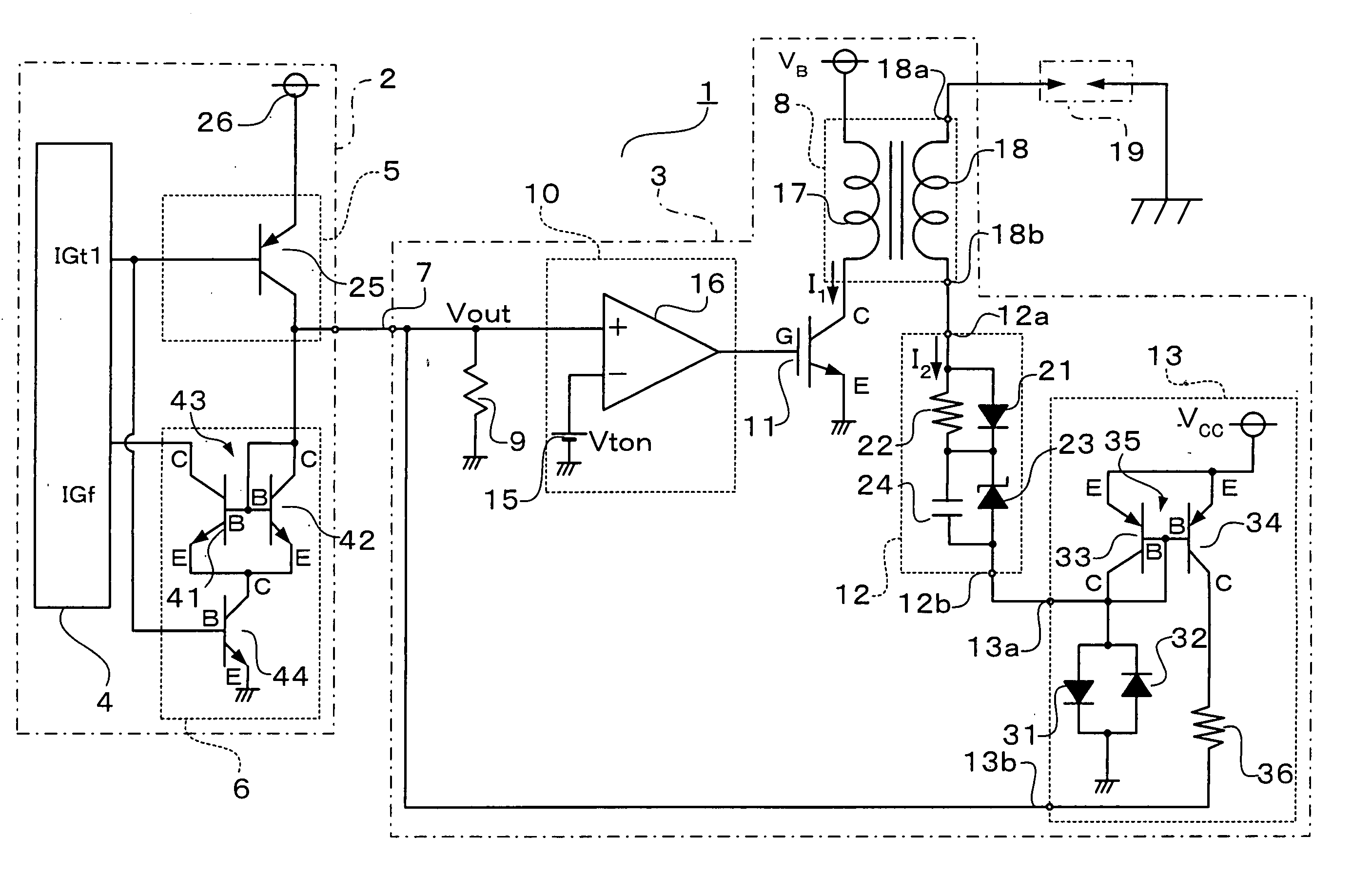
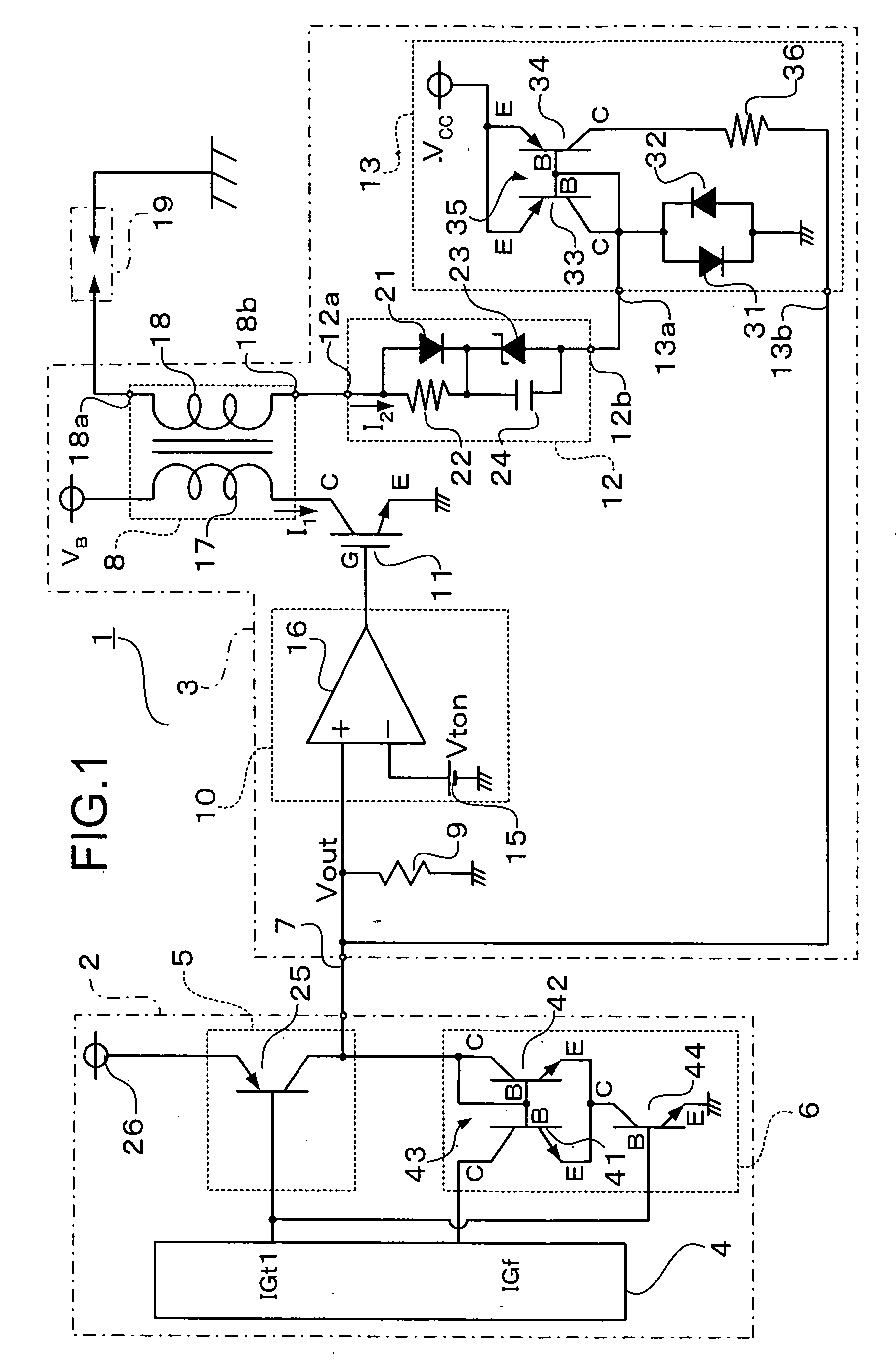
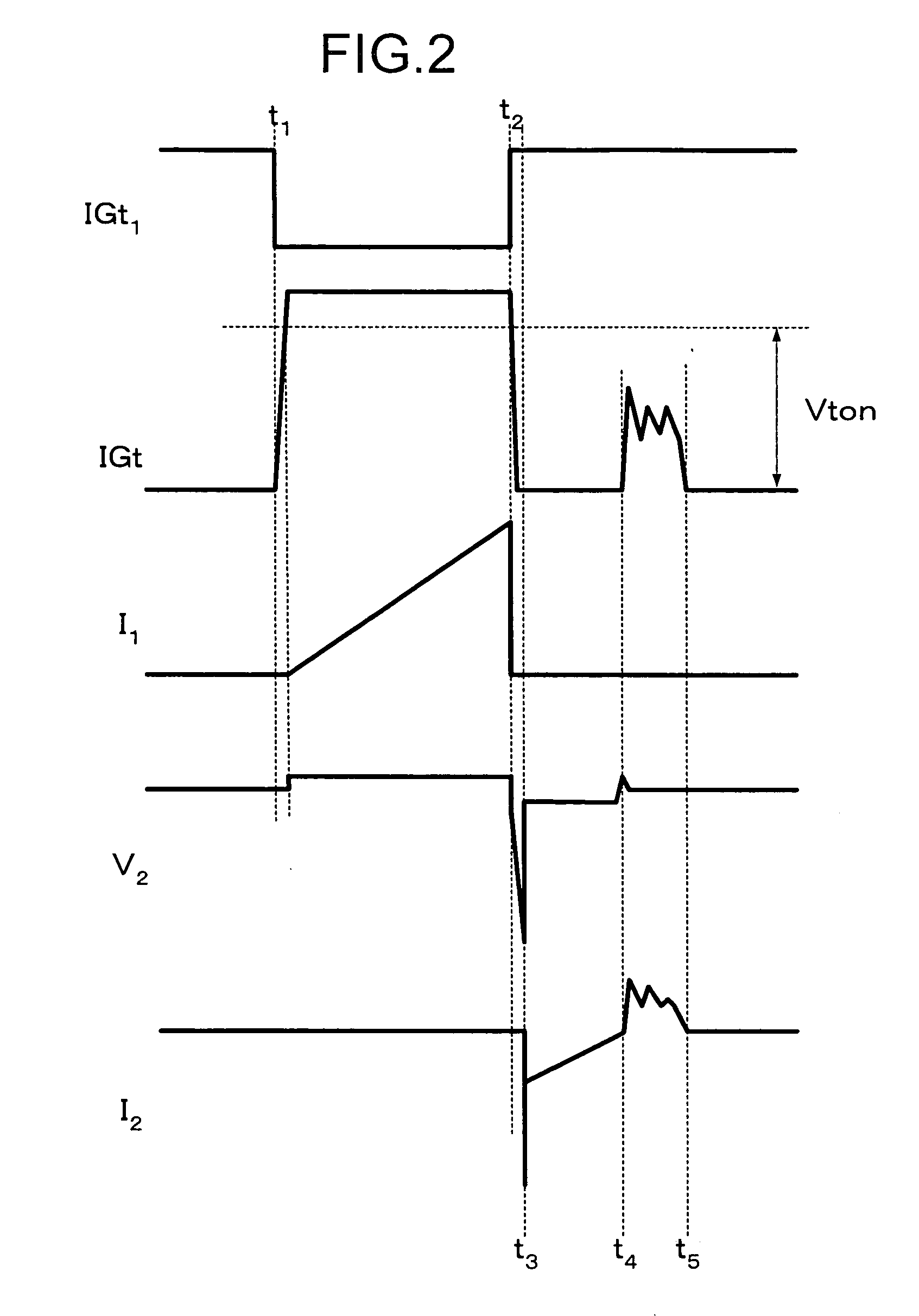
[0015]FIG. 1 is a circuit diagram of an ignition apparatus for an internal combustion engine according to a first embodiment of the present invention. FIG. 2 shows timing charts of signals at respective portions of the ignition apparatus for the internal combustion engine according to the first embodiment of the present invention.

[0016] An ignition apparatus 1 for an internal combustion engine (hereinafter referred to simply as the “ignition apparatus 1”) according to the first embodiment of the present invention is designed as an ignition apparatus for an internal combustion engine mounted in an automobile. As shown in FIG. 1, the ignition apparatus 1 is composed of an electronic control unit 2 (hereinafter referred to as the “ECU 2”) and an igniter 3.

[0017] The ECU 2 has a processing unit 4, an ignition signal driving circuit 5, and an ion control circuit 6.

[0018] The processing unit 4 sends out an ignition command signal IGt1 at a desired timing, for example, at a time point t...

second embodiment

[0049]FIG. 3 is a circuit diagram of an ion current detecting / outputting circuit 13B according to a second embodiment of the present invention.

[0050] As shown in FIG. 3, the ion current detecting / outputting circuit 13B according to the second embodiment of the present invention is different from the ion current detecting / outputting circuit 13 according to the first embodiment of the present invention in that a group of a plurality of transistors 34B is employed instead of the transistor 34, and in that a base current compensating transistor 37 for compensating for a base current flowing through the group of the transistors 34B is added. Since they are identical in other respects, the same description will be omitted by allocating like reference symbols to like components.

[0051] An emitter of the base current compensating transistor 37 is connected to a base of the transistor 33, a base of the base current compensating transistor 37 is connected to a collector of the transistor 33,...

third embodiment

[0053]FIG. 4 is a circuit diagram of an ignition apparatus 1C for an internal combustion engine (hereinafter referred to simply as the “ignition apparatus 1C”) according to a third embodiment of the present invention.

[0054] As shown in FIG. 4, the ignition apparatus 1C according to the third embodiment of the present invention is different from the ignition apparatus 1 according to the first embodiment of the present invention in that a power supply circuit 50 is added, and in that an ion current detecting / outputting circuit 13C and a first constant current circuit 14 as an electric load are employed instead of the ion current detecting / outputting circuit 13 and the input resistor 9, respectively. Since they are identical in other respects, the same description will be omitted by allocating like reference symbols to like components.

[0055] The first constant current circuit 14 causes a constant current to flow from the power supply 26 to the transistor 25 and the signal line 7 when...


PUM


Abstract

The ignition apparatus includes an electronic control unit and an igniter. The igniter detects ions resulting from ignition, and sends an ion current output signal to the electronic control unit. The igniter has a waveform shaping circuit and an ion current detecting / outputting circuit. The waveform shaping circuit is adapted such that a voltage at an input terminal thereof becomes higher than a predetermined reference voltage to turn the switching element ON when the ignition signal is caused to flow through an electric load. The ion current detecting / outputting circuit has an output terminal which is connected to the input terminal and outputs therefrom an ion current output signal obtained as a result of conversion of an ion current, and is adjusted such that the voltage at the input terminal at the time when the ion current output signal is outputted to the electronic control unit becomes lower than the reference voltage.

Description

BACKGROUND OF THE INVENTION [0001] 1. Field of the Invention [0002] The present invention relates to an ignition apparatus for an internal combustion engine mounted in, for example, an automobile, and more particularly to an ignition apparatus for an internal combustion engine in which a high voltage for ignition is generated in a secondary coil of an ignition coil by allowing and shutting off a flow of a current to a primary coil of the ignition coil by means of a switching element. [0003] 2. Description of the Related Art [0004] A conventional ignition apparatus for an internal combustion engine is provided with resistors through which a current corresponding to an ion current and a current of an ignition signal are caused to flow, respectively, a comparator for comparing voltages generated in the resistors with each other, and a switch for making a switchover between the current of the ignition signal and the current corresponding to the ion current based on a result of the compa...

Claims


Application Information

Patent Timeline
IPC IPC(8): F02P3/05
CPCF02P17/12F02P2017/125
Inventor NARUSE, YUSUKEOKAMURA, KOICHI
Owner MITSUBISHI ELECTRIC CORP
Learn More