Valve for a fluid flow connector having an overmolded plunger

a technology of fluid flow connector and plunger, which is applied in the field of flexible packaging, can solve the problems of affecting the taste of dispensed soft drinks, affecting the taste of liquid beverages, and leaking of fluid connectors, and achieves the effect of less swelling

Active Publication Date: 2007-06-21
RAPAK INC
View PDF50 Cites 23 Cited by
  • Summary
  • Abstract
  • Description
  • Claims
  • Application Information

AI Technical Summary

Benefits of technology

[0013] One embodiment of the present invention includes a fluid flow connector having an adapter for attaching the fluid flow connector to a spout of a fluid container. The fluid flow connector also includes a valve that is actuated to allow flow through the connector when the connector is attached to the spout of the fluid container. The valve includes a plunger that has a hard core and a soft exterior that is overmolded to the hard core. The hard core of the plunger is made of a thermoplastic material and the soft exterior is made of a thermoplastic elastomer that will provide a fluid tight seal with the inlet of the fluid flow connector.
[0014] One of the advantages of the present invention is that because the plunger is formed by overmolding, EPDM O-rings do not have to be used in the valve to provide a fluid tight seal with the inlet of the fluid flow connector. The present invention can thus provide a fluid flow connector that does not utilize EPDM O-rings which have a tendency to swell when the fluid flow connectors are used in applications having diet soft drink syrup.
[0015] For example, in one study completed by the applicant, plungers were manufactured for fluid flow connectors consisting of soft exteriors made of Santoprene™ TPV 271-55 which were overmolded to hard cores made of polyoxymethylene copolymer. The results of the study showed that the soft exteriors of the plungers embodying the present invention had significantly less swelling than did the EPDM O-ring of prior art plungers when the fluid connectors were used in applications having diet soft drink syrup. The present invention can thus be utilized for a significantly longer period of time without encountering the problems which occur from connectors having swollen O-rings.

Problems solved by technology

This swelling causes the fluid connectors to leak because the O-rings can no longer provide a fluid tight seal when the connectors are not connected to the containers.
The leaking fluid flow connectors also lets air into the fountain dispensing machines, causing a loss of vacuum or suction and, in some cases, an adverse effect on the taste of the dispensed soft drinks.
The swelling of the O-rings additionally creates another problem; the swollen O-rings decrease the flow rate through the fluid flow connectors when the connectors are attached to the spouts of containers and fluid is being dispensed from the containers.
The above-described problems generate increased operating costs for the soft drink syrup suppliers who have to make additional service calls to soda fountain retailers to repair leaking fluid flow connectors.
Moreover, fountain soda retailers incur increased operating costs because of the clean-up of leaked syrup caused by the leaking fluid connectors.
The retailers also lose sales of diet fountain soda while waiting for the leaking fluid flow connectors to be repaired or from the connectors not being able to dispense the syrup properly.

Method used


Image

  • Valve for a fluid flow connector having an overmolded plunger
  • Valve for a fluid flow connector having an overmolded plunger
  • Valve for a fluid flow connector having an overmolded plunger

Examples


Embodiment Construction

[0029] While this invention includes embodiments in many different forms, the embodiments shown in the drawings and described herein are preferred embodiments. Those preferred embodiments are to be considered exemplifications of the principles of the invention and are not intended to limit the broad aspect of the invention to the embodiments illustrated and described herein.

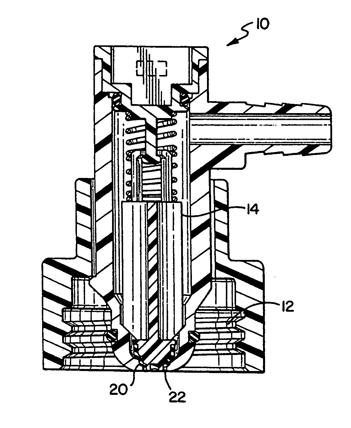
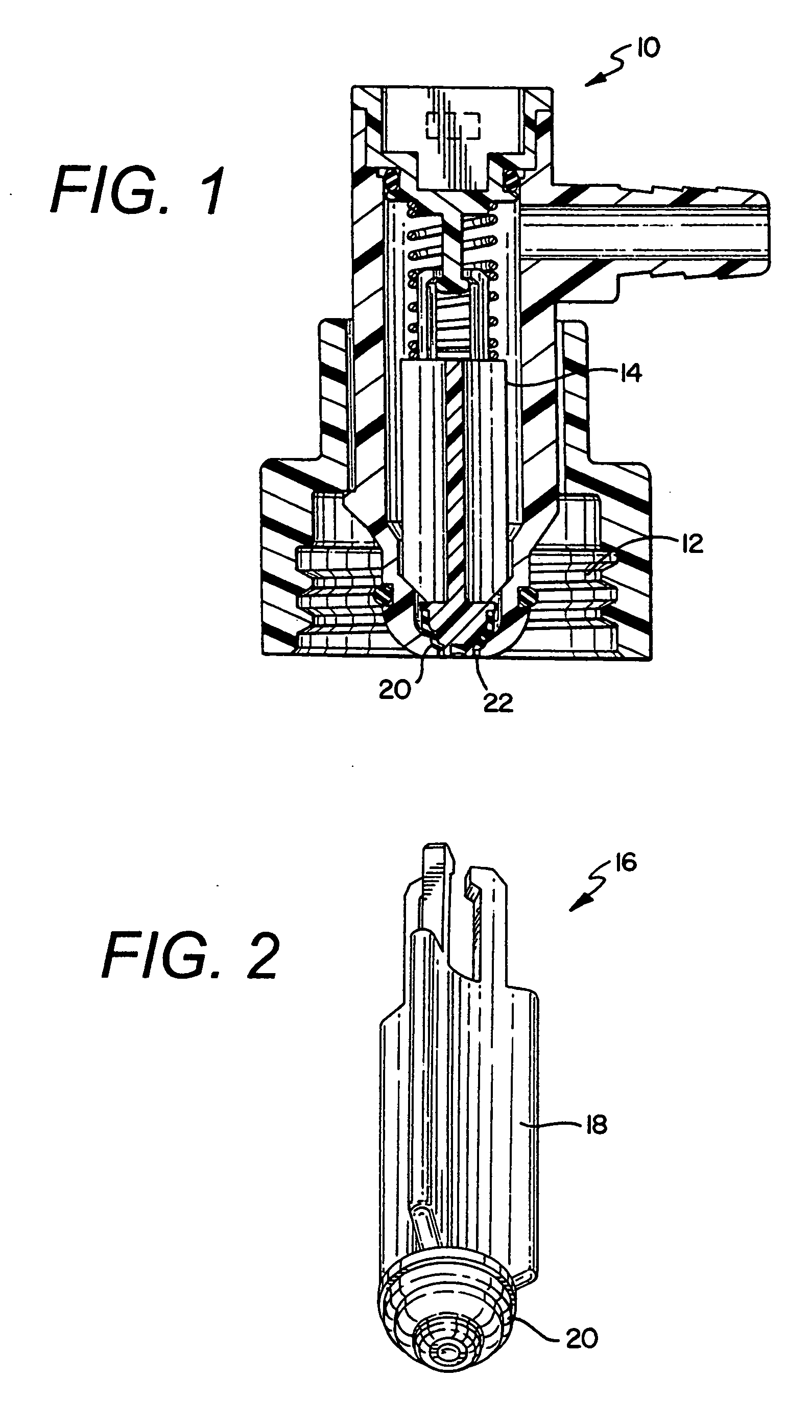
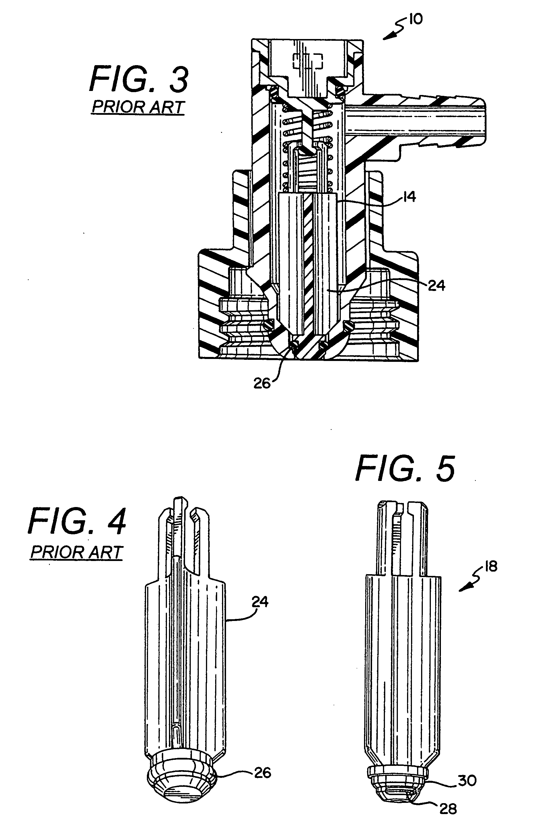
[0030] The present invention is directed to a fluid flow connector 10 having an adapter 12 for attaching the fluid flow connector 10 to a spout of a fluid container. One embodiment of the present invention is illustrated in FIG. 1. The fluid flow connector 10 also includes a valve 14 that is actuated to allow flow through the connector 10 when the connector 10 is attached to the spout of the fluid container. The valve 14 includes a plunger 16 that has a hard core 18 and a soft exterior 20 that is overmolded to the hard core 18. One embodiment of plunger 16 is illustrated in FIG. 2. In that embodiment of the pres...


PUM

PropertyMeasurementUnit
forceaaaaaaaaaa
actuating forceaaaaaaaaaa
swellingaaaaaaaaaa

Abstract

A fluid flow connector and a method of manufacturing the same wherein the fluid flow connector utilizes a valve having a plunger which is made by overmolding a soft exterior to a hard core. The soft exterior being overmolded to the hard core by either insert or multi-shot methods. The method also including attaching the soft exterior to the hard core mechanically and / or by molecular bonding.

Description

TECHNICAL FIELD [0001] The invention relates generally to flexible packaging and more specifically to the fluid connectors used to connect the flexible packaging to their end uses. BACKGROUND OF THE INVENTION [0002] A number of flexible plastic containers are well known in the art for storing and dispensing wine, soft drink syrup, dairy products, enteral feeding solutions, fruit juices, tea and coffee concentrates, puddings, cheese sauces, cleaning chemicals and many other flowable materials. The flexible containers described above typically have walls fabricated from polymeric films having either a monolayer or multiple layer structure. The particular polymers constituting the container film layers will often vary depending upon the type of material to be placed in the container. [0003] In some instances, the film layers may additionally include an oxygen barrier material layer to prevent contact between such materials and oxygen or other gas sensitive contents. In some application...

Claims


Application Information

Patent Timeline
Patent Type & Authority Applications(United States)
IPC IPC(8): F16K51/00F16L29/00
CPCB29C45/1676F16K27/0209F16K15/063B29L2031/7506
Inventor SMITH, MARK A.
Owner RAPAK INC
Why Eureka
Try Eureka