Wind energy harnessing apparatuses, systems, methods, and improvements

Inactive Publication Date: 2007-06-21
REIDY MICHAEL
View PDF52 Cites 110 Cited by
  • Summary
  • Abstract
  • Description
  • Claims
  • Application Information

AI Technical Summary

Benefits of technology

[0011] In addition, some embodiments provide as an object or benefit, for example, that they provide a wind turbine in which the propeller turns at a higher speed so that a speed increaser is not required or need not increase the speed as much, proportionally, particularly while addressing other objects or potential areas for benefit. Furthermore, some embodiments provide as an object or benefit, for instance, that they provide a wind turbine having smaller blades or provide a venturi that increases wind velocity and that has a shape that reduces losses as air passes through the ventu

Problems solved by technology

In addition to the traditional pollutants from burning of fossil fuels, such as hydrocarbons, carbon monoxide, particulates, and acid rain, as examples, use of wind energy reduces the production of greenhouse gasses (i.e., carbon dioxide), in comparison with fossil fuels, and the contribution to the risks and potential harm associated with global warming.
However, certain locations are far better than others for locating devices that harness wind energy, and available locations with adequate and relatively consistent wind speeds are limited.
Consequently, the number of wind turbines that have been installed in a particular area of land has been rather limited.
But towers are expensive to build and, at least in some cases, their height may be objectionable, for example, for obstructing a view.
In addition, flying birds are often killed or injured by traditional exposed wind turbines, and needs and potential for benefit exist, especiall

Method used


Image

  • Wind energy harnessing apparatuses, systems, methods, and improvements
  • Wind energy harnessing apparatuses, systems, methods, and improvements
  • Wind energy harnessing apparatuses, systems, methods, and improvements

Examples


Embodiment Construction

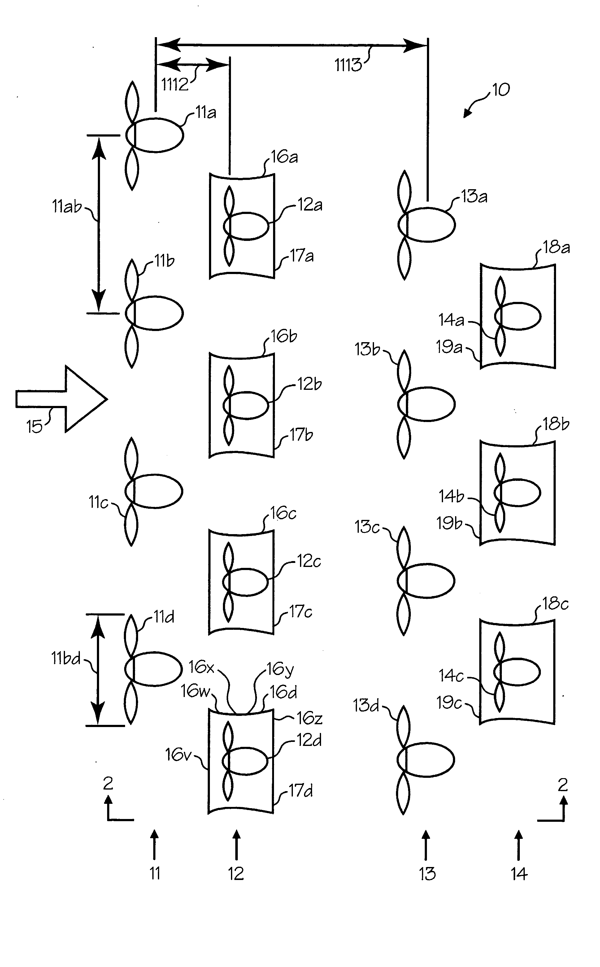
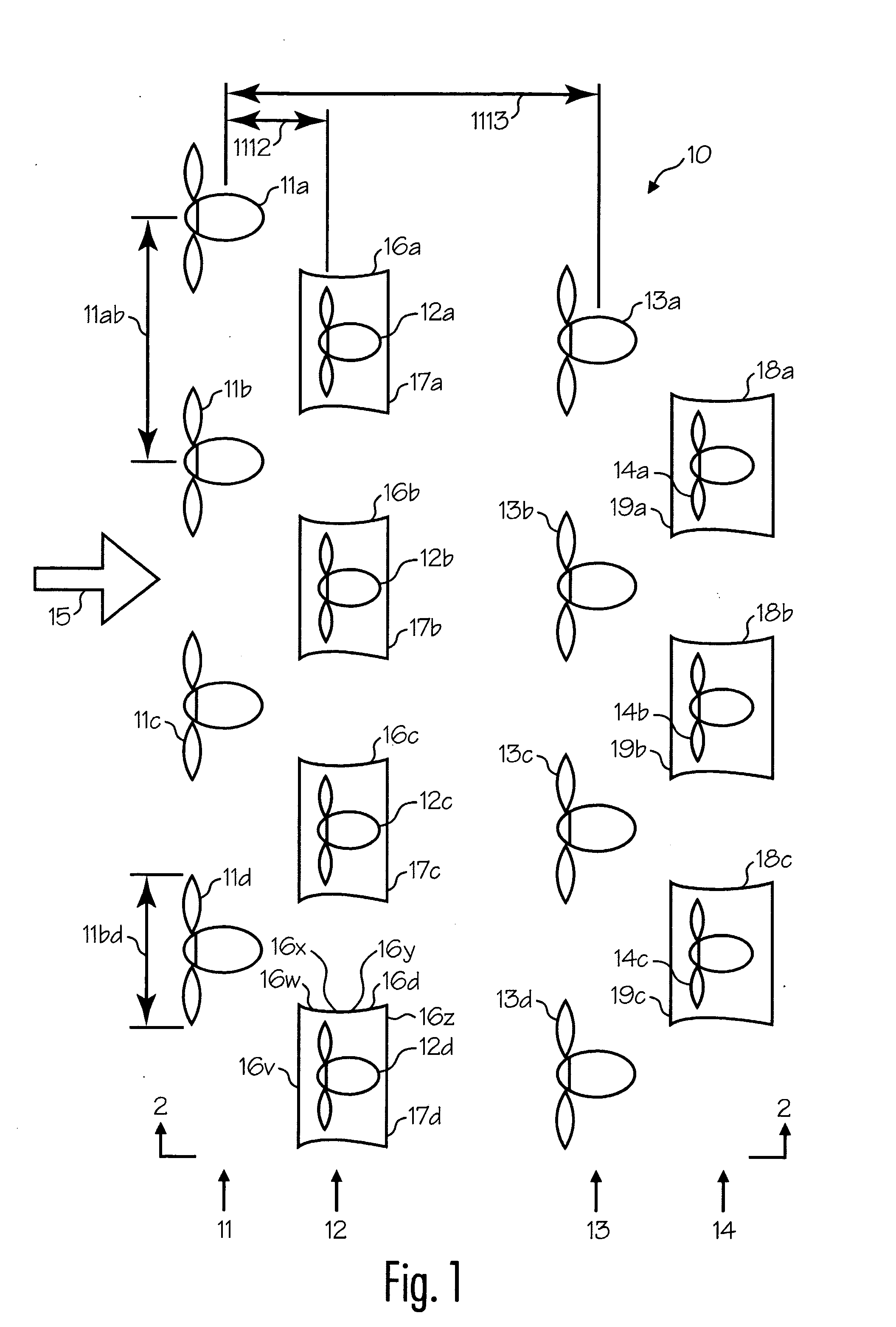
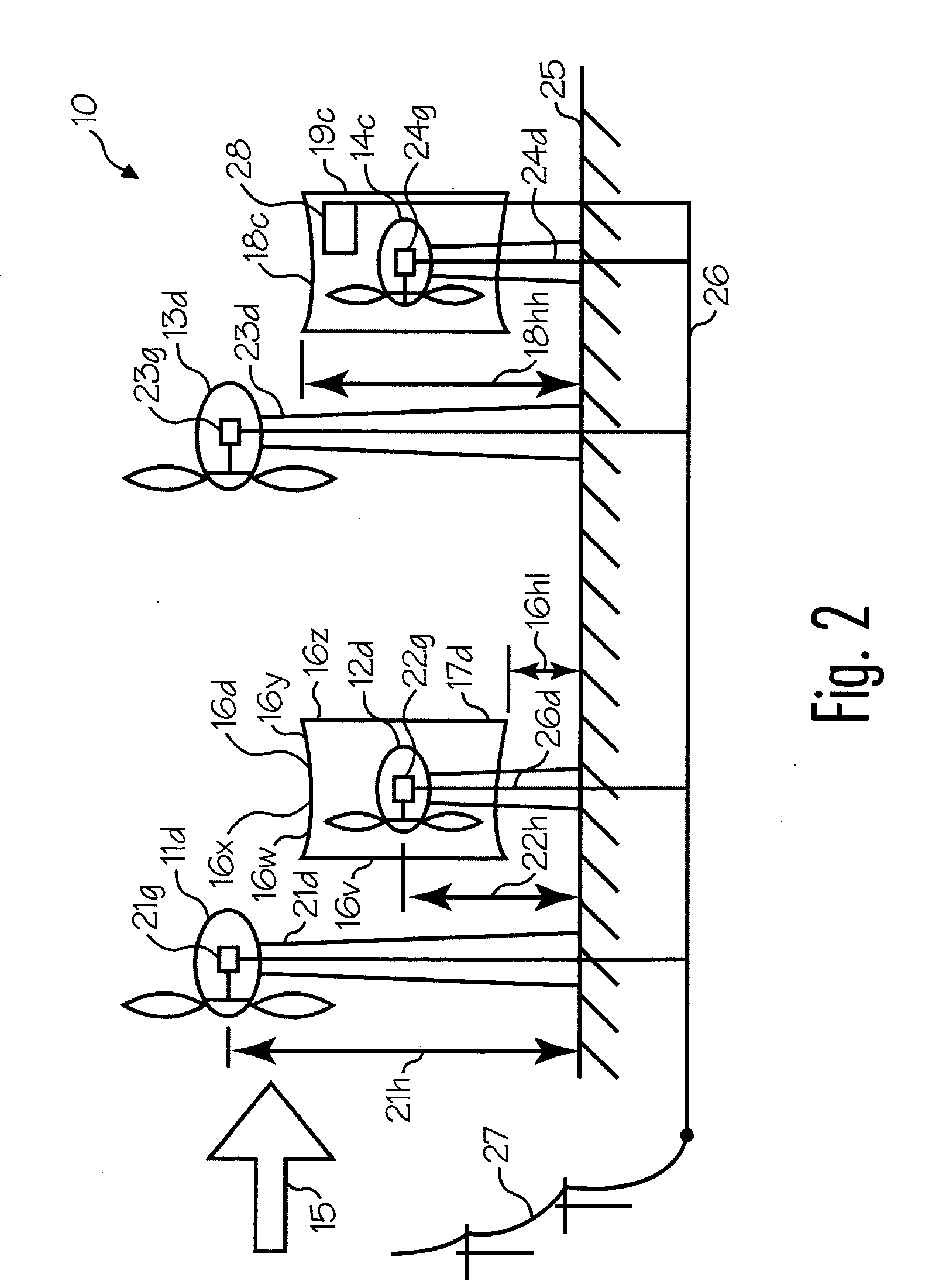
[0010] This invention provides, among other things, methods of improving the power production capability of a new or existing wind farm, wind farms for generating electricity from wind, and various apparatuses for harnessing wind energy. Various embodiments of the invention provide as an object or benefit that they partially or fully address one or more of the needs, potential areas for improvement or benefit, or functions described herein, for instance. Specific embodiments provide as an object or benefit, for instance, that they increase or improve the power production capability of a new or existing wind farm, or of a particular area of available land, or allow greater power production per area of land, more wind turbines per area of land, or less interference between adjacent wind turbines. In some embodiments, an object or benefit may be to install at least some wind turbines at locations within the wind farm where wind speeds are relatively high.

[0011] In addition, some embod...


PUM


Abstract

Improvements to wind farms and wind generators for harnessing wind energy or generating electricity from wind. Secondary wind turbines are provided at particular locations within a wind farm to generate additional electricity, in some embodiments, using a common electrical power collection system. Enclosures or venturis may surround wind turbines to facilitate mounting close to the ground. Venturis may accelerate wind speed through the turbine and may have a particular shape, may be made of particular materials arranged in particular ways, or both. In different embodiments, wind turbines may be axial-flow horizontal-axis turbines, or may be Savonius turbines, as examples. And in some embodiments, wind turbines may be combined with other power production equipment, such as solar power equipment, for instance.

Description

CLAIM OF PRIORITY [0001] This patent application claims priority to, and incorporates by reference, U.S. provisional patent application 60 / 729,053, titled: Venturi Wind Generator, by Mike Reidy, which was filed on Oct. 20, 2005.FIELD OF INVENTION [0002] This invention relates to apparatuses, systems, and methods for harnessing renewable sources of energy including wind energy, and improvements thereto. Particular embodiments relate to wind turbines and wind farms for producing electricity from wind energy. BACKGROUND OF THE INVENTION [0003] Wind energy has been harnessed for centuries and used for a variety of useful purposes including propelling sailing ships to newly discovered continents, grinding grain, pumping water, and generating electricity. In recent times, large propeller-type horizontal axis turbines have been mounted on towers and used to turn electrical generators to provide a portion of the power for a large electrical distribution grid. Significant numbers of these wi...

Claims


Application Information

Patent Timeline
IPC IPC(8): F03D9/00H02P9/04
CPCF03D9/00F03D9/005F03D9/007F05B2240/133F05B2240/213F05B2240/96F05B2250/25Y02E10/725F03D9/257Y02E10/72Y02E10/74F03D13/20F03D9/34F03D1/04F03D3/0427F03D3/02H02S10/12Y02E10/50Y02P80/10
Inventor REIDY, MICHAEL T.IYER, HARI S.MONTTINEN, JARMO
Owner REIDY MICHAEL
Why Eureka
Try Eureka