Wiring structure of vibrator, and piezoelectric pump

Inactive Publication Date: 2007-06-21
ALPS ALPINE CO LTD
View PDF7 Cites 27 Cited by
  • Summary
  • Abstract
  • Description
  • Claims
  • Application Information

AI Technical Summary

Benefits of technology

[0017] Moreover, the bimorph-type piezoelectric element formed in a circular shape in plan view is provided at a peripheral edge thereof with a spacer insulating ring made of a rubber material which determines the total thickness of the bimorph-type piezoelectric

Problems solved by technology

Meanwhile, in a piezoelectric vibrator in which vibrations having an amplitude of 1 mm or less (in the order of 100 μm) are repeated, it was found that poor connection occurs in soldered portions between the film-like electrodes on

Method used


Image

  • Wiring structure of vibrator, and piezoelectric pump
  • Wiring structure of vibrator, and piezoelectric pump
  • Wiring structure of vibrator, and piezoelectric pump

Examples


Embodiment Construction

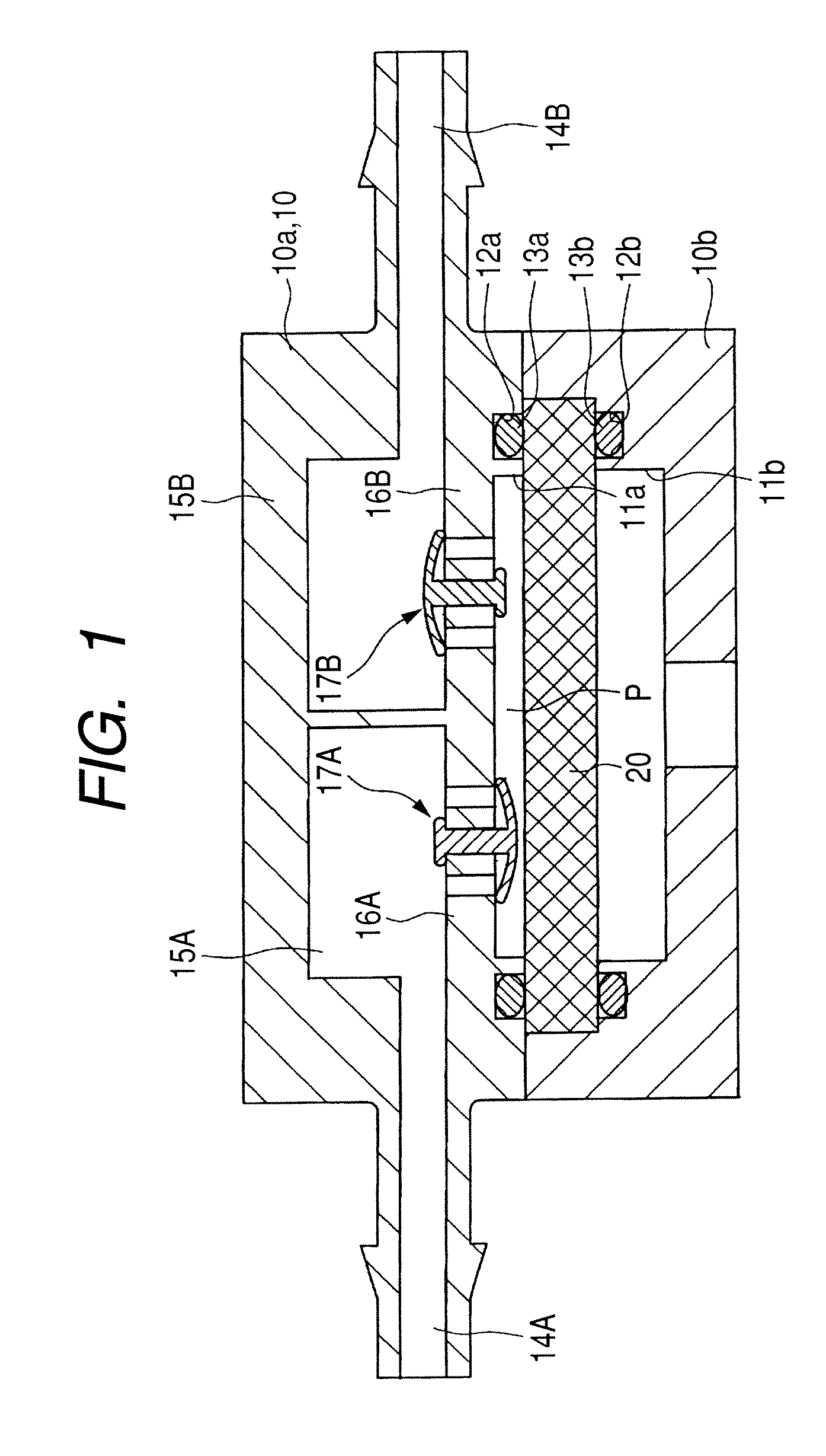
[0024] The illustrated embodiment is an embodiment in which the invention is applied to a piezoelectric pump, and the principle of the piezoelectric pump is shown in FIG. 1. A housing 10 is composed of an upper housing 10a and a lower housing 10b. Both the housings 10a and 10b are formed with recessed parts 11a and 11b and seal ring grooves 12a and 12b along the recessed parts 11a and 11b in their facing surfaces, respectively. A piezoelectric vibrator 20 is sandwiched between the upper housing 10a and the lower housing 10b by causing the front and back sides thereof to abut on seal rings 13a and 13b inserted into the seal ring grooves 12a and 12b, respectively, and a variable volume chamber P is formed between the recessed part 11a and the piezoelectric vibrator 20. Although a variable volume chamber is also formed between the recessed part 11b and the piezoelectric vibrator 20, this chamber does not have a pumping action. Although the thickness of the piezoelectric vibrator 20 is ...


PUM


Abstract

The invention relates a wiring structure of a vibrator and a piezoelectric pump. On the basis of the recognition that it is difficult to obtain sufficient reliability of connecting parts with a conductive adhesive material only while attention is paid to using the conductive adhesive material instead of soldering, a wiring structure is obtained in which a connecting terminal and a film-like electrode are adhered to each other by a conductive adhesive material, and a pressing member which applies a force in a direction in which the connecting terminal is pressed against the film-like electrode is caused to abut on the connecting terminal.

Description

[0001] This application claims the benefit of Japanese Patent Application No. 2005-361151, filed on Dec. 15, 2005, the contents of which is incorporated herein by reference. BACKGROUND OF THE INVENTION [0002] 1. Field of the Invention [0003] The present invention relates to a wiring structure of a vibrator and a piezoelectric pump having the wiring structure. [0004] 2. Description of the Related Art [0005] As an apparatus having a vibrator, there is, for example, a piezoelectric pump. In the piezoelectric pump, a pumping action is obtained by forming a variable volume chamber between a flat plate-like piezoelectric vibrator and a housing, and by vibrating the piezoelectric vibrator to change the volume of the variable volume chamber. More specifically, a pair of flow channels connected with the variable volume chamber is provided with a pair of check valves (a check valve which allows flow of fluid to the variable volume chamber and a check valve which allows flow of fluid from the ...

Claims


Application Information

Patent Timeline
IPC IPC(8): H01L41/08
CPCF04B43/04F04B43/046H01L41/047H10N30/875
Inventor ISHIKAWA, JUNYAMADA, SATOSHI
Owner ALPS ALPINE CO LTD
Why Eureka
Try Eureka