Optical system and optical apparatus including optical system

Inactive Publication Date: 2007-06-21
CANON KK
View PDF5 Cites 12 Cited by
  • Summary
  • Abstract
  • Description
  • Claims
  • Application Information

AI Technical Summary

Benefits of technology

[0019]At least one exemplary embodiment is directed to an optical system capable of appropriately cor

Problems solved by technology

In general, compact optical systems having a short lens length tend to suffer from a greater amount of aberration, in particular, a greater amount of longitudinal and lateral chromatic aberration, resulting in lower optical performance.
In particular, the amount of chromatic aberration is increased in optical systems having a shortened lens length.
Since optical systems of the negative-lead type have a lens unit with a negative refractive power in the anterior position, negative distortion can easily occur.
However, glass having a high refractive index generally has a high dispersion, and easily causes a greater amount of negative lateral chromatic aberration.
Moreover, it is very difficult to machine anomalous partial dispersion glass such as fluorite.
Furthermore, the specific gravity of the material is relative

Method used


Image

  • Optical system and optical apparatus including optical system
  • Optical system and optical apparatus including optical system
  • Optical system and optical apparatus including optical system

Examples


first exemplary embodiment

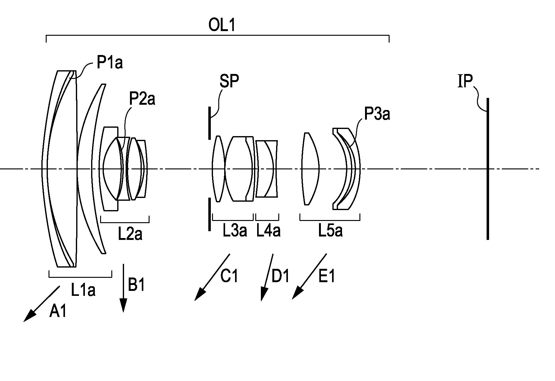
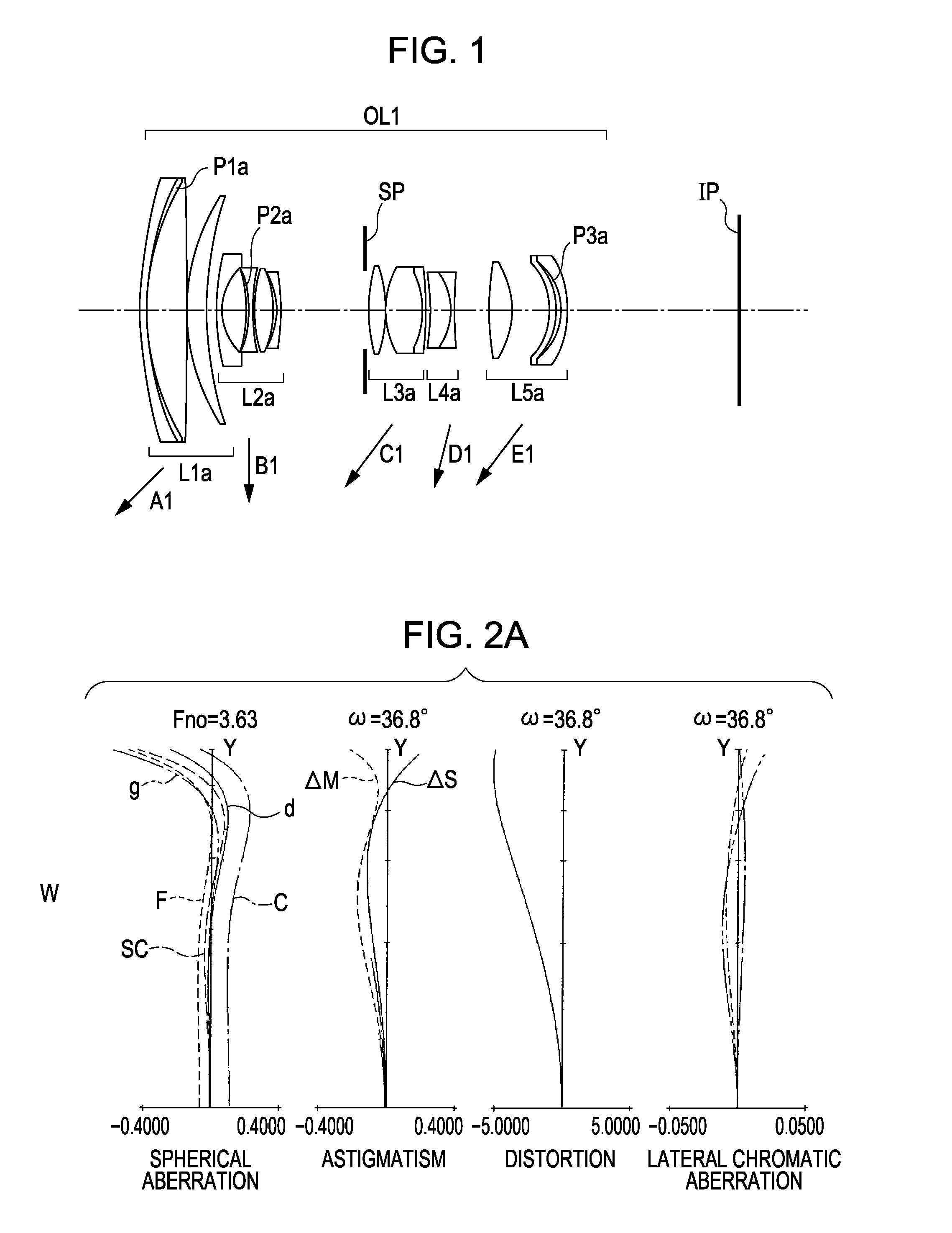
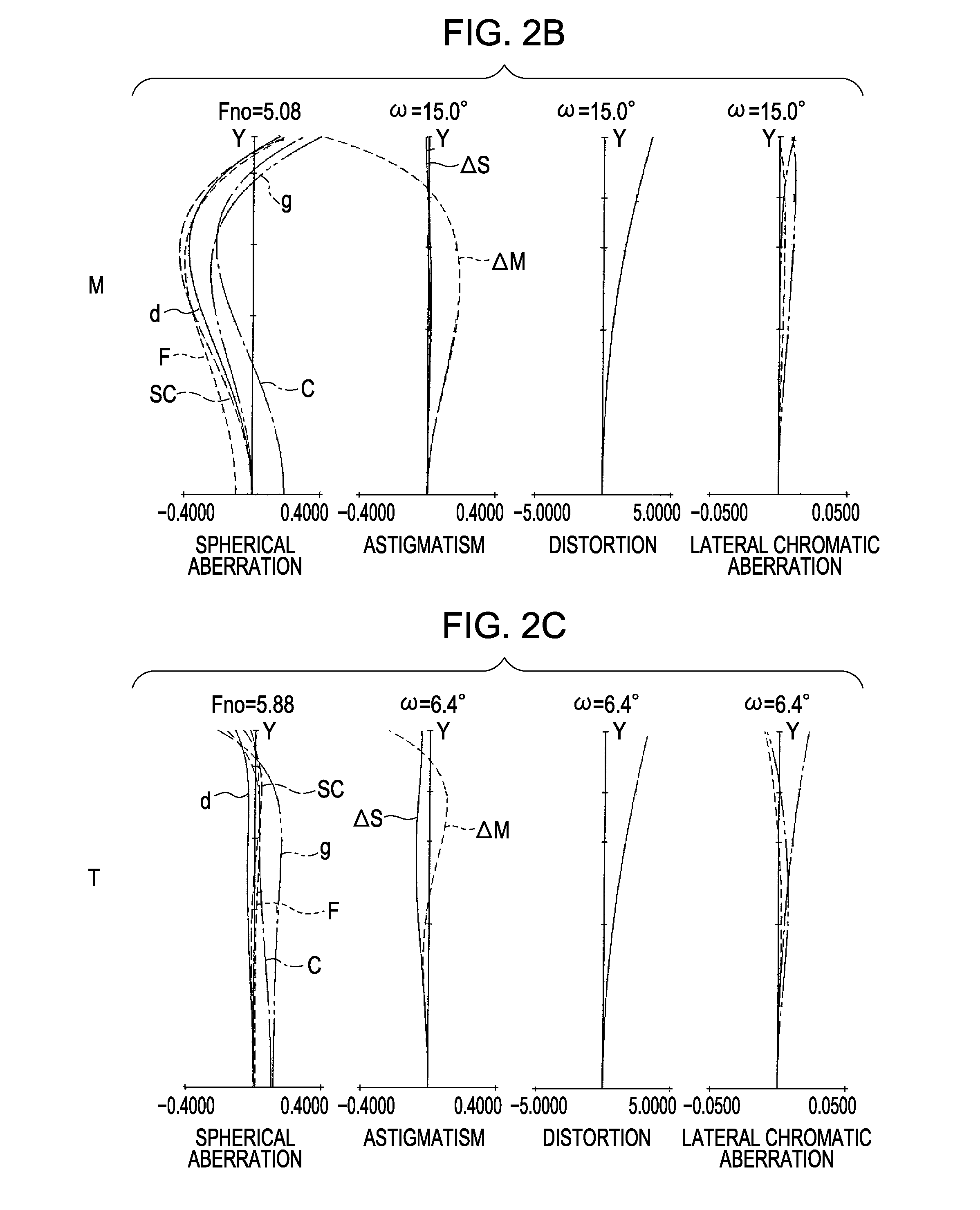
[0042]FIGS. 1, 3, 5, and 7 are cross-sectional views of lenses at a wide-angle end. FIGS. 2A to 2C, 4A to 4C, 6A to 6C, and 8A to 8C illustrate aberration at the wide-angle end (A), at an intermediate position of a zoom range (B), and at a telephoto end (C). FIGS. 10 and 12 illustrate aberration when a focus of an optical system is adjusted to an object at infinity.

[0043]Optical systems (e.g., OL1-OL6) according to exemplary embodiments of the present invention can be used for imaging and / or optical apparatus (e.g., silver-salt film cameras, digital still cameras, video cameras, telescopes, binoculars, projectors, copying machines, and other optical apparatus as known by one of ordinary skill in the relevant arts). In the cross-sectional views of the lenses, the left side is adjacent to an object (the anterior position), and the right side is adjacent to an image-taking side (the posterior position).

[0044]When the optical systems according to the exemplary embodiments of the present...

numerical example 1

[0099]

f=28.90˜193.15Fno=3.63˜5.88 2ω=73.6˜12.8

R1=102.694D1=1.50N1=1.846660ν1=23.9

R2=67.525D2=0.05N2=1.578566ν2=16.5

R3=57.448D3=9.29N3=1.603112ν3=60.6

R4=−938.598D4=0.12

R5=48.476D5=4.44N4=1.622992ν4=58.2

R6=82.382D6=variable

*R7=73.541D7=1.20N5=1.834807ν5=42.7

R8=13.885D8=5.65

R9=−33.988D9=0.60N6=1.578566ν6=16.5

R10=−24.239D10=1.00N7=1.834807ν7=42.7

R11=52.693D11=0.12

R12=30.334D12=4.52N8=1.755199ν8=27.5

R13=−21.950D13=0.60

R14=−17.654D14=0.90N9=1.772499ν9=49.6

R15=−69.021D15=variable

R16=SP D16=0.94

R17=43.224D17=4.08N10=1.487490ν10=70.2

R18=−30.236D18=0.15

R19=26.744D19=8.13N11=1.487490ν11=70.2

R20=−21.083D20=0.90N12=1.805181ν12=25.4

R21=−63.759D21=variable

R22=−51.876D22=4.69N13=1.740769ν13=27.8

R23=−14.998D23=0.90N14=1.882997ν14=40.8

R24=123.097D24=variable

R25=85.239D25=5.21N15=1.583126ν15=59.4

*R26=−20.371D26=8.80

R27=−15.933D27=1.50N16=1.698947ν16=30.1

R28=−16.645D28=1.01N17=1.635550ν17=22.7

R29=−14.231D29=1.50N18=1.805181ν18=25.4

R30=−24.910[0100]\Focal length 28.90 80.81 193.15[0101]Variable gap\[010...

numerical example 2

[0109]

f=28.90˜193.17Fno=3.63˜5.88 2ω=73.6˜12.8

R1=132.527D1=1.50N1=1.846660ν1=23.9

R2=49.733D2=2.52N2=1.635550ν2=22.7

R3=67.379D3=7.08N3=1.622992ν3=58.2

R4=984.359D4=0.12

R5=51.358D5=7.04N4=1.622992ν4=58.2

R6=234.151D6=variable

*R7=73.837D7=1.20N5=1.834807ν5=42.7

R8=14.793D8=5.59

R9=−44.796D9=0.21N6=1.578566ν6=16.5

R10=−37.512D10=1.00N7=1.834807ν7=42.7

R11=45.257D11=0.12

R12=27.772D12=4.32N8=1.755199ν8=27.5

R13=−30.460D13=1.02

R14=−19.218D14=0.90N9=1.772499ν9=49.6

R15=101.774D15=2.03N10=1.784723ν10=25.7

R16=−93.904D16=variable

R17=SP D17=0.70

R18=34.666D18=4.41N11=1.518229ν11=58.9

R19=−28.082D19=0.15

R20=37.367D20=4.95N12=1.517417ν12=52.4

R21=−20.919D21=0.30N13=1.635550ν13=22.7

R22=−18.412D22=0.90N14=1.846660ν14=23.9

R23=−118.206D23=variable

R24=−39.813D24=2.43N15=1.728250ν15=28.5

R25=−18.948D25=0.90N16=1.882997ν16=40.8

R26=−97.865D26=variable

R27=52.675D27=6.09N17=1.583126ν17=59.4

*R28=−20.674D28=1.27

R29=315.706D29=2.16N18=1.487490ν18=70.2

R30=−126.226D30=3.07

R31=−21.208D31=1.00N19=1.834000ν19=37.2

R32=284.744D...


PUM


Abstract

At least one exemplary embodiment is directed to an optical system which includes at least one first refractive optical element, which includes a solid material satisfying the following conditional expression (1), and at least one second refractive optical element, which includes a solid material satisfying the following conditional expression (2):
−1.33×10⁻³×νd+6.7×10⁻¹<θgF   (1)
−1.63×10⁻³×νd+6.2×10⁻¹>θgF   (2)
where νd and θgF indicate the Abbe number and the partial dispersion ratio, respectively.

Description

BACKGROUND OF THE INVENTION[0001]1. Field of the Invention[0002]The present invention relates to optical systems and optical apparatuses including the optical systems.[0003]2. Description of the Related Art[0004]To date, optical systems having a short lens length (optical length; length from a first lens adjacent to an object to an image plane) have been demanded for optical apparatuses such as digital still cameras, video cameras, and projectors.[0005]In general, compact optical systems having a short lens length tend to suffer from a greater amount of aberration, in particular, a greater amount of longitudinal and lateral chromatic aberration, resulting in lower optical performance.[0006]In particular, the amount of chromatic aberration is increased in optical systems having a shortened lens length.[0007]Well-known optical systems include lens systems of a so-called negative-lead type having a lens unit with a negative refractive power disposed in the anterior position and a lens ...

Claims


Application Information

Patent Timeline
IPC IPC(8): G02B9/34
CPCG02B13/02G02B15/173G02B27/0062G02B15/144511G02B15/145121G02B15/146
Inventor MISAKA, MAKOTO
Owner CANON KK
Why Eureka
Try Eureka