Electrical cabinet including a wiring support
a technology of electrical cabinets and wiring supports, applied in the field of electrical cabinets, can solve the problems of requiring a great deal of time, one of the most time-consuming and delicate steps, and the most common redundancy of the electrical network in the aircraft, so as to reduce the effect of further reducing the distance between the two bars
- Summary
- Abstract
- Description
- Claims
- Application Information
AI Technical Summary
Benefits of technology
Problems solved by technology
Method used
Image

Examples
first embodiment
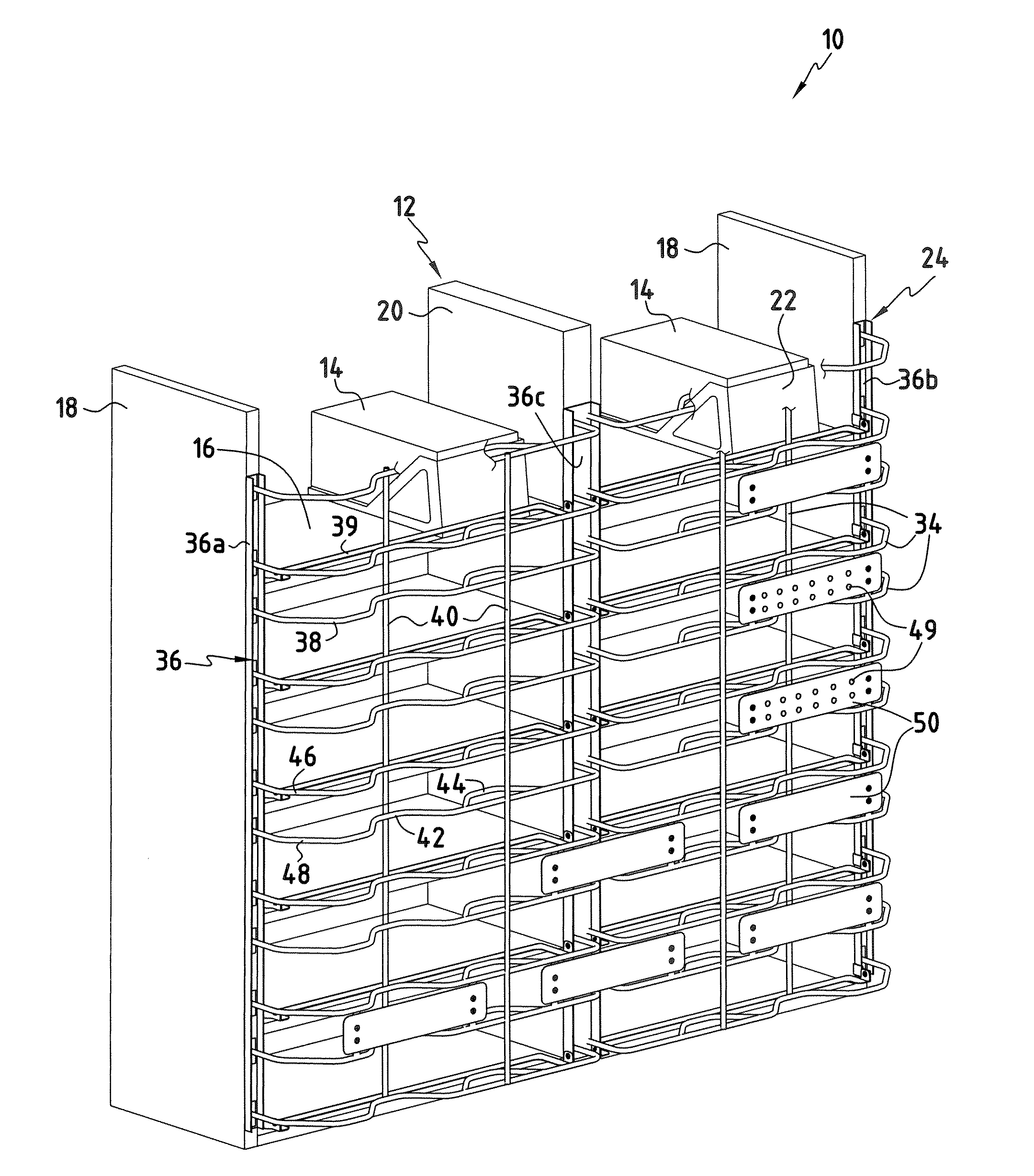
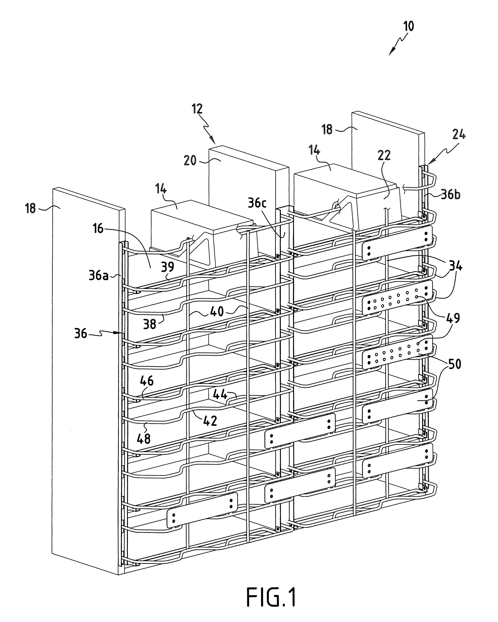
[0090] FIGS. 1 to 5 illustrate the electrical cabinet according to the invention.
[0091]FIG. 1 depicts an electrical cabinet 10 including an enclosure 12 designed to house a plurality of electrical equipment units 14. Such equipment units 14 are already known in the field of aircraft engineering. They may for example comprise computers, radios or any other type of electrical or electronic equipment.
[0092] The enclosure 12 is preferably a shelf unit which in this example includes six shelves 16 each extending in a horizontal plane.
[0093] The shelves are held in place by two lateral uprights 18 and a central upright 20, which extend vertically.
[0094] Each of the shelves 16 has a sufficient depth to accommodate the electrical equipment units 14.
[0095] The electrical cabinet according to the invention is not in any way limited to the use of a shelf unit. It is perfectly possible to use other types of enclosure or housing structure capable of receiving electrical equipment, without ex...
second embodiment
[0153] With reference to FIGS. 6 to 10, the electrical cabinet according to the invention will now be described.
[0154] The second embodiment includes certain elements already described in the first embodiment. These identical elements have the same numerical reference as that of the element described in the first embodiment, increased by one hundred.
[0155] In this second embodiment, the enclosure 112 of the cabinet 110 is the same as that used in the first embodiment. However, the electrical cabinet 110 is designed to house electrical equipment units 114 requiring three different signals, that is to day the wiring support carries six routes for reasons of redundancy.
[0156] For the sake of legibility, the cable bundles are not shown in FIG. 6.
[0157]FIG. 7 depicts the wiring support 124 of the second embodiment of the electrical cabinet 110 according to the invention.
[0158] The wiring support 124 also takes the form of a grid including support elements arranged cross-wise in the f...
third embodiment
[0187] With reference to FIGS. 11 to 15, the electrical cabinet according to the invention will now be described.
[0188] The third embodiment includes certain elements already described in the first two embodiments These identical elements have the same numerical reference as that of the element described in the first embodiment, increased by two hundred.
[0189]FIG. 11 depicts the electrical cabinet 210 according to the third embodiment of the invention.
[0190] The shelf unit 212, the metal carriers 222 and the electrical equipment units 214 have already been described for the first two embodiments.
[0191] The essential difference in this case lies in the wiring support 224, which can be clearly seen in FIG. 12.
[0192] The wiring support 224 is formed by two identical or symmetrical assemblies, referred to as chassis 270, 272, arranged side by side in a manner such that the wiring support 224 presents a vertical plane of symmetry.
[0193]FIG. 12 shows a first chassis 270 and a second ...
PUM
 Abstract
- an enclosure (12) designed to house a plurality of electrical equipment units (14),
- a plurality of electrical cable bundles attached to a face of the enclosure (12) for the electrical connection of said electrical equipment units (14),
Description
Claims
Application Information
 - R&D Engineer
- R&D Manager
- IP Professional
- Industry Leading Data Capabilities
- Powerful AI technology
- Patent DNA Extraction
Browse by: Latest US Patents, China's latest patents, Technical Efficacy Thesaurus, Application Domain, Technology Topic.
© 2024 PatSnap. All rights reserved.Legal|Privacy policy|Modern Slavery Act Transparency Statement|Sitemap