Backlight assembly

a backlight and assembly technology, applied in the field of backlights, can solve the problems of limited application of backlight assembly in electronic devices, current demand for smaller and lighter electronic devices, and problems such as leakage current, and achieve the effect of minimizing leakage current and improving the luminous efficiency of lamps

Inactive Publication Date: 2007-06-21
LG DISPLAY CO LTD
View PDF4 Cites 6 Cited by
  • Summary
  • Abstract
  • Description
  • Claims
  • Application Information

AI Technical Summary

Benefits of technology

[0023] The present embodiments may obviate one or more problems due to limitations and disadvantages of the related art. For example, in one embodiment, a backlight assembly is capable of improving the luminous efficiency of a lamp by minimizing a leakage current.

Problems solved by technology

However, there is currently a demand for the smaller and lighter electronic devices.
Because of the large size and weight of the CRT its application in electronic devices is limited.
As illustrated in FIG. 2, the backlight assembly is problematic in that a leakage current occurs when an AC voltage is applied to the lamp.
Accordingly, the leakage current causes the brightness of the lamp to decrease, thus lowering the luminous efficiency of the lamp and degrading the quality of an image.
The present embodiments may obviate one or more problems due to limitations and disadvantages of the related art.

Method used


Image

  • Backlight assembly
  • Backlight assembly
  • Backlight assembly

Examples


Embodiment Construction

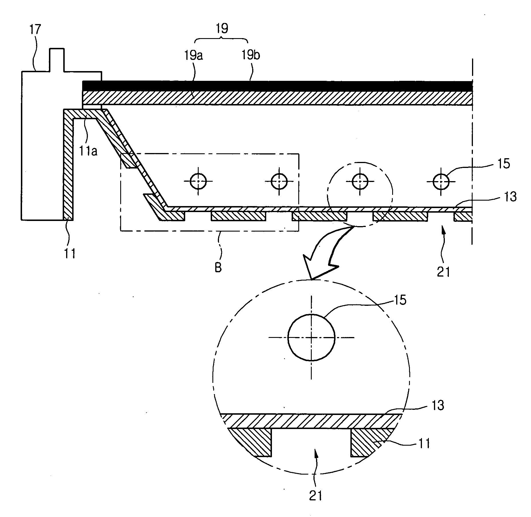
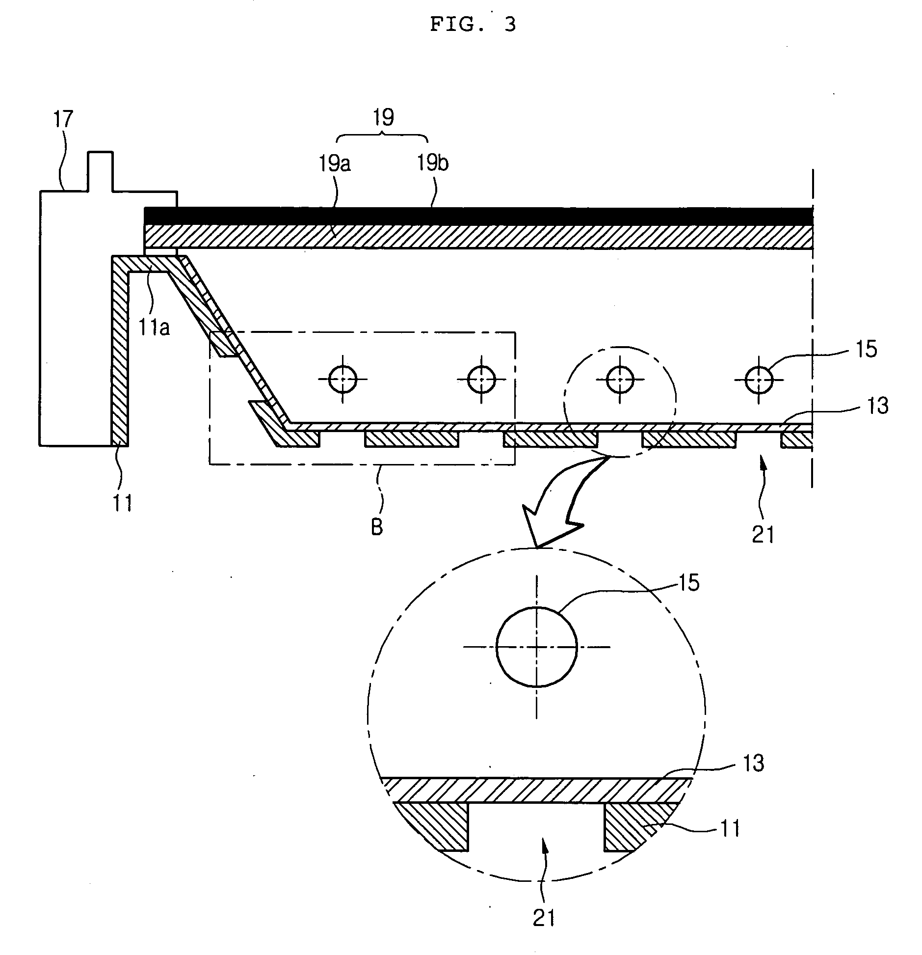
[0034] In one embodiment, as illustrated in FIG. 3, the backlight assembly includes a plurality of lamps 15 disposed on the same plane over a cover bottom 11. The lamps 15 may be fixed to the cover bottom 11 using a lamp holder (not shown) or the like. Each of the lamps 15 may be a cold cathode fluorescence lamp (CCFL), an external electrode fluorescence lamp (EEFL) or a plurality of light emitting diodes. An optical sheet 19 is disposed over the plurality of lamps 15 at a predetermined interval from the lamps 15.

[0035] The optical sheet 19 includes a diffusion sheet 19aand a prism sheet 19b. Bank 11a is formed at both sides of the cover bottom 11 to space the optical sheet 19 apart from the lamps 15. Each bank 11a protrudes from a bottom of the cover bottom 11 to a predetermined height. The optical sheet 19 is mounted on the bank 11a. A reflector sheet 13 that reflects light is attached on an upper surface of the cover bottom 11. The optical sheet 19 is fixed and supported by a pa...


PUM


Abstract

A backlight assembly is provided. The backlight assembly includes a plurality of lamps and a plurality of holes in a cover bottom that correspond to the plurality of lamps. The backlight may be capable of improving luminous efficiency of a plurality of lamps is provided.

Description

[0001] This Non-provisional Application claims priority under 35 U.S.C. §119(a) on Patent Application No. 125901 / 2005, filed on Dec. 20, 2005, the entire contents of which are hereby incorporated by reference. BACKGROUND [0002] 1. Field [0003] The present embodiments relate to a backlight. [0004] 2. Related Art [0005] A cathode ray tube (CRT) is widely used for a television (TV), a monitor of a measuring instrument, an information terminal, or the like. However, there is currently a demand for the smaller and lighter electronic devices. Because of the large size and weight of the CRT its application in electronic devices is limited. [0006] As a substitute for the CRT, smaller, lighter and thinner display devices have received much attention. For example, a liquid crystal display (LCD) device, a plasma display panel (PDP), and an electro luminescence display (ELD) have all been used as a substitute for the CRT. [0007] The LCD device has advantages of low power consumption and full co...

Claims


Application Information

Patent Timeline
Patent Type & Authority Applications(United States)
IPC IPC(8): F21V7/04G09F13/04
CPCG02F1/133604G02F1/133608G02F2001/133612G02F1/133612G02F1/1335
Inventor HAN, YOUNG BAE
Owner LG DISPLAY CO LTD
Why Eureka
Try Eureka