
Method and system for multiple-input-multiple-output (MIMO) communication in a wireless network

Active Publication Date: 2007-06-21
SASKEN COMMUNICATION TECHNOLOGIES
View PDF9 Cites 8 Cited by
  • Summary
  • Abstract
  • Description
  • Claims
  • Application Information

AI Technical Summary

Benefits of technology

[0009] An object of the invention is to improve the capacity of MIMO systems by reducing inter-antenna correlation between the channels of different pairs of the base station and the user-equipment antennas. Another object of the invention is to provide a MIMO system that can function with the data of one or more user-equipments. Still another object of the invention is to provide a MIMO system in which the number of antennas transmitting or receiving is greater than the number of users communicating at a certain period, in a slot that can be a time, frequency, code or any other similar slot.
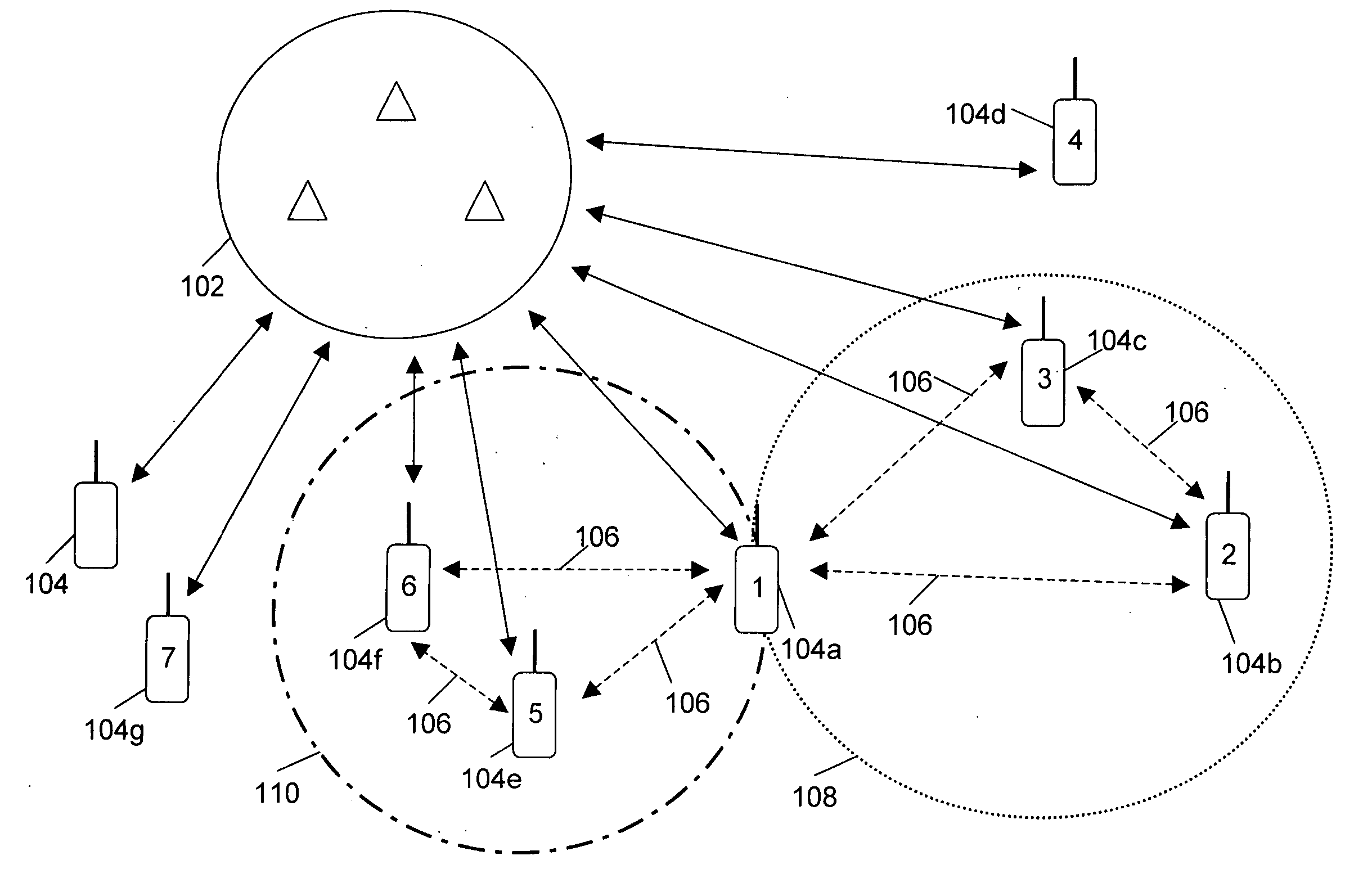
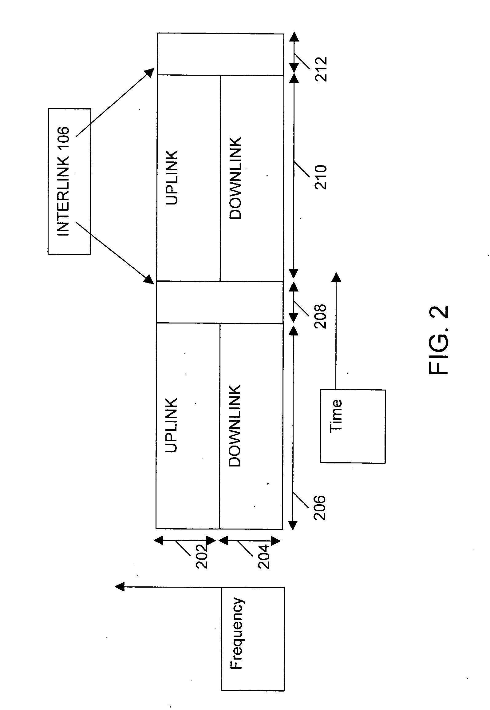
[0011] During uplink communication, the data of the first user-equipment is split and processed into several streams, based on the number of user-equipments in the first set. A first stream is transmitted by the first user-equipment to the base stations in a slot assigned for uplink communication of the first user-equipment. The remaining streams are transmitted, one each to the user-equipments in the first set on an Interlink, which facilitates communication between the various user-equipments. These remaining streams are then transmitted by the user-equipments in the first set to the base stations in the same slot as that used for the transmission of the first stream.

Problems solved by technology

Due to the severe space constraints in user-equipment, it is not possible to accommodate a large number of sufficiently spaced antennas that are uncorrelated with each other.
However, the method operates well only when the transmitter at the base station has the complete channel state information.
However, the method operates satisfactorily only when channel state information is available at the base station.
Moreover, as the streams transmitted by different antennas are correlated, beamforming cannot achieve the full capacity offered by MIMO communications.

Method used


Image

  • Method and system for multiple-input-multiple-output (MIMO) communication in a wireless network
  • Method and system for multiple-input-multiple-output (MIMO) communication in a wireless network
  • Method and system for multiple-input-multiple-output (MIMO) communication in a wireless network

Examples


Embodiment Construction

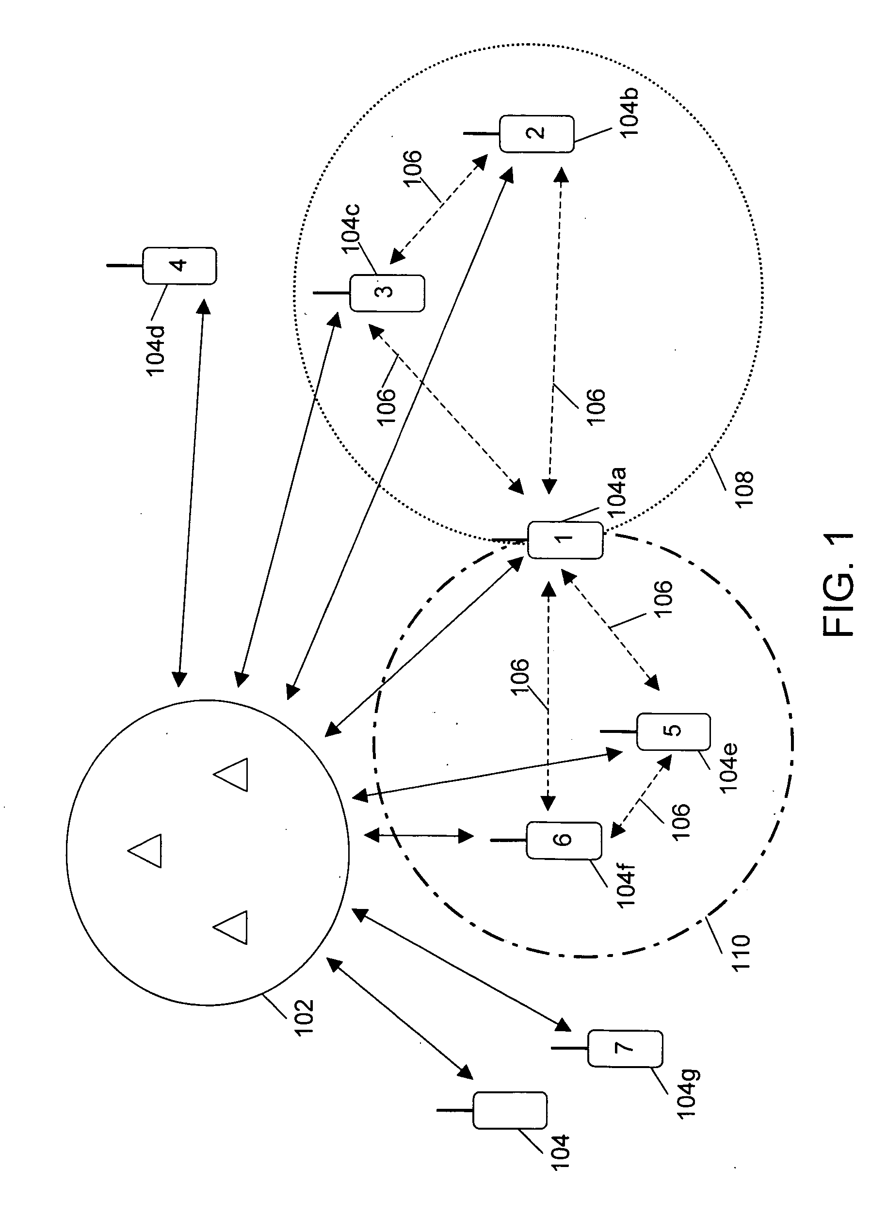
[0025]FIG. 1 illustrates a system for the communication of data in a wireless network, in accordance with an embodiment of the invention. The wireless network comprises base stations 102 and user-equipments 104. Base stations 102 may have multiple antennas for communicating data with user-equipments 104. In various embodiments of the invention, each user-equipment 104 may have one or more antennas. Examples of user-equipments 104 include cellular phones, transportable phones, portable phones, and personal digital assistants (PDAs), among others.

[0026] User-equipments 104 are capable of communicating with base stations 102. In various embodiments of the invention, base stations 102 and user-equipments 104 can communicate using Time Division Multiple Access (TDMA), Code Division Multiple Access (CDMA) and Frequency Division Multiple Access (FDMA), among others. According to an embodiment of the invention, one or more of user-equipments 104 communicate with each other on an Interlink ...


PUM


Abstract

A method and a system for Multiple-Input-Multiple-Output (MIMO) communication in a wireless network are provided. According to the method, streams of the data of a user-equipment are communicated to a group of user-equipments that act as antennas for the user-equipment. The communication between the various user-equipments is through an Interlink. The data of the user-equipment is communicated with base stations by the user-equipment and the group of user-equipments in a single slot.

Description

REFERENCE TO RELATED APPLICATIONS [0001] This application claims the priority of Indian patent application 1843 / CHE / 2005, which was filed with the Indian Patent Office on Dec. 15, 2005. BACKGROUND OF THE INVENTION [0002] The invention generally relates to wireless networks. More specifically, the invention relates to multiple-input-multiple-output (MIMO) communication in wireless networks. [0003] A MIMO wireless communication system comprises multiple antennas at the transmitter and the receiver. The use of multiple antennas increases the transmission capacity of the system as compared to a single-input-single-output (SISO) system. Thereby, increasing the number of users as well as the amount of data that can be sent by each user. [0004] The antennas work best in a multi-path environment such that the streams, in which the data is transmitted and received, are uncorrelated. Closely spaced antennas in user-equipment lead to increased correlation between the data streams that are comm...

Claims


Application Information

Patent Timeline
IPC IPC(8): H04J3/00H04Q7/00
CPCH04B7/026H04B7/0669H04B7/0671
Inventor VARIKAT, ANUBALA
Owner SASKEN COMMUNICATION TECHNOLOGIES
Learn More