Decoding apparatus and decoding method

Inactive Publication Date: 2007-06-21
KK TOSHIBA
View PDF20 Cites 76 Cited by
  • Summary
  • Abstract
  • Description
  • Claims
  • Application Information

AI Technical Summary

Benefits of technology

[0009]The present invention is directed to a decoding apparatus and a decoding meth

Problems solved by technology

In this case, mosquito noise means ringing noise.
However, if decoded image quality estimated by the coding i

Method used


Image

  • Decoding apparatus and decoding method
  • Decoding apparatus and decoding method
  • Decoding apparatus and decoding method

Examples


Embodiment Construction

[0025]Hereinafter, various embodiments of the present invention will be explained by referring to the drawings. The present invention is not limited to the following embodiments.

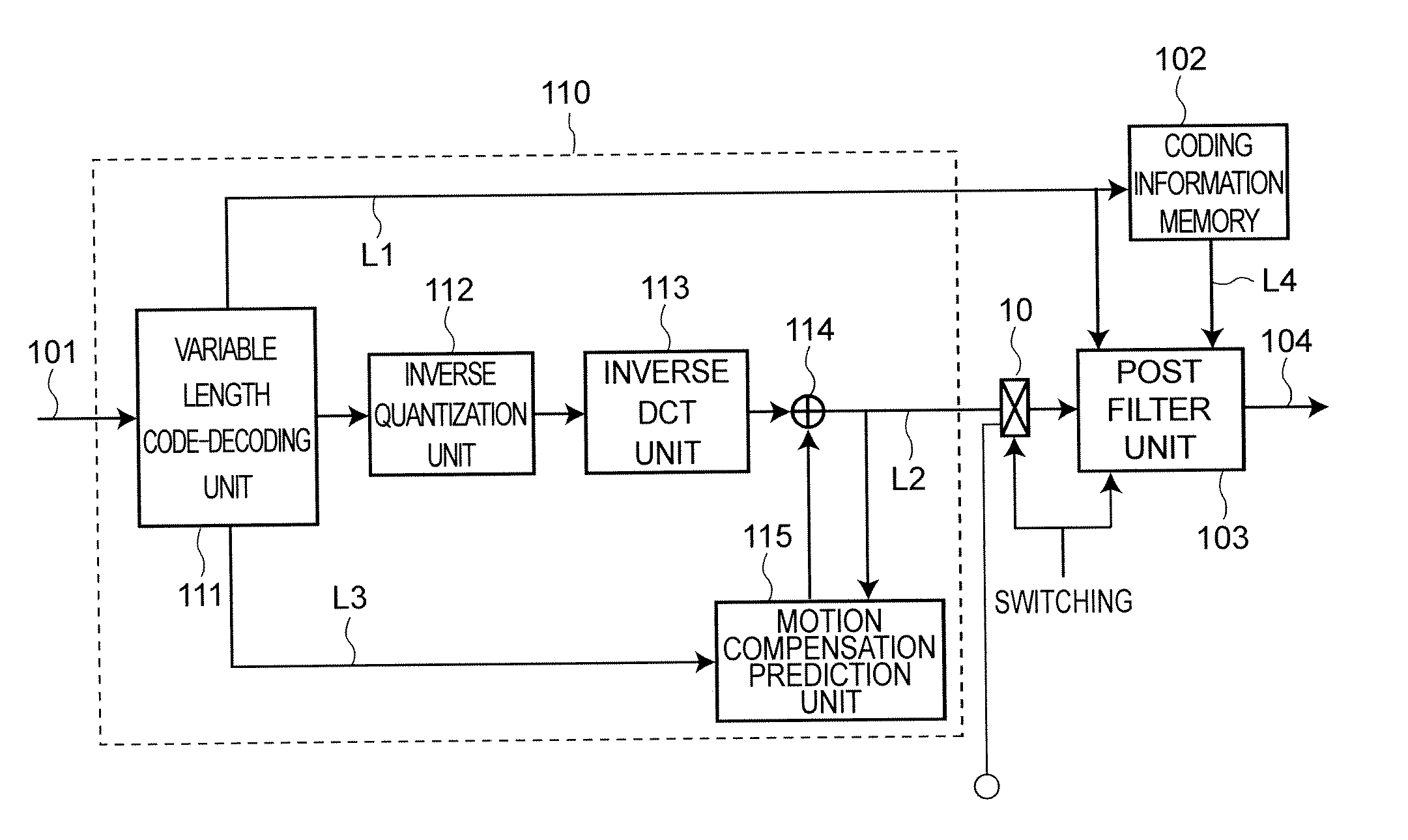
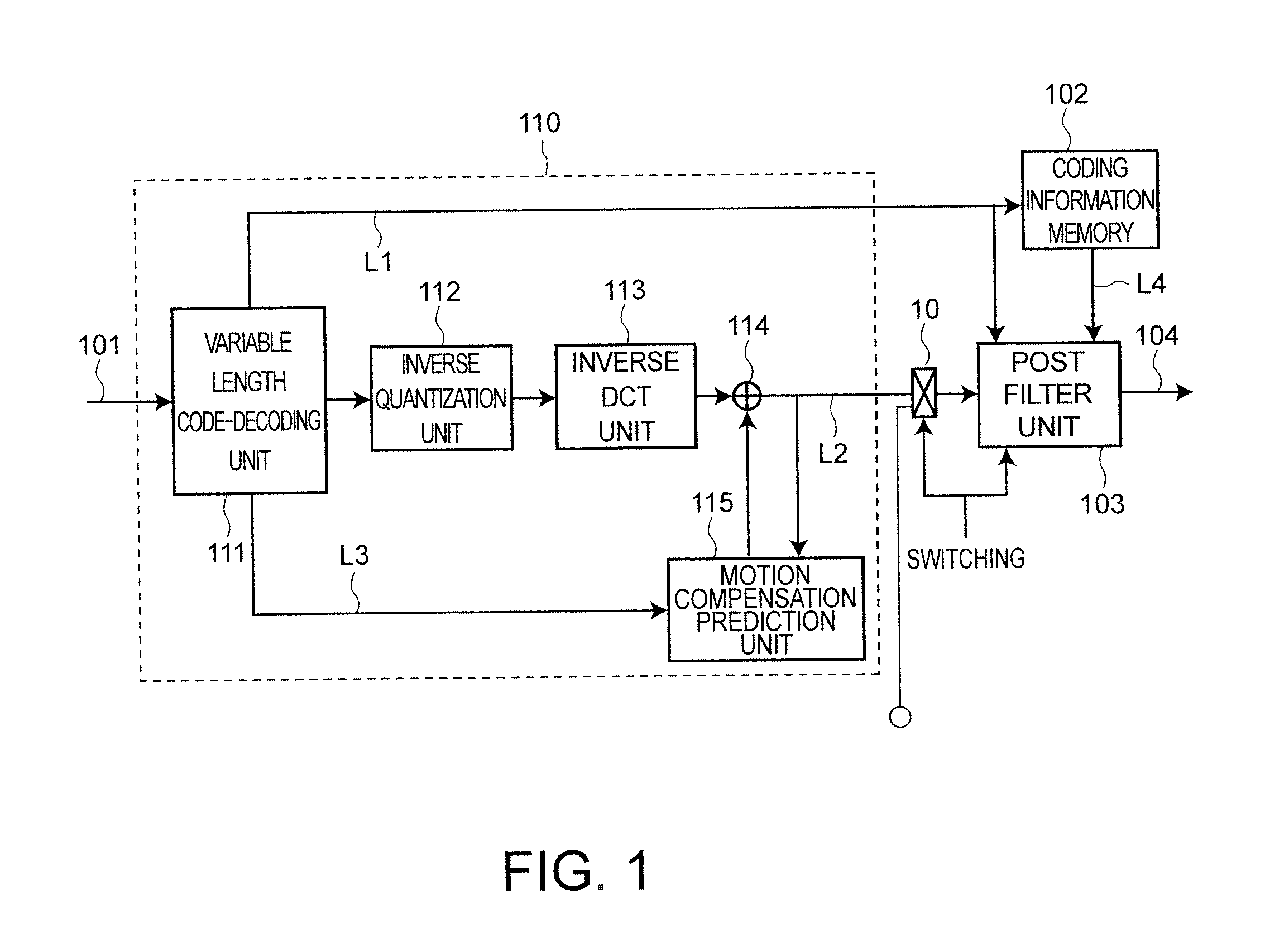
[0026]FIG. 1 is a block diagram of a decoding apparatus according to one embodiment of the present invention. In the present embodiment, processing of the decoding apparatus is explained using a bit stream of MPEG-2. However, a bit stream of coding method using another MC and DCT may be used.

[0027]As shown in FIG. 1, the decoding apparatus includes a video decoding unit 110, a post filter unit 103, and a coding information memory 102. The video decoding unit 110 includes a variable length code-decoding unit 111, an inverse quantization unit 112, an inverse DCT unit 113, an adder 114, and a motion compensation prediction unit 115.

[0028]Furthermore, a switchover unit 10 is set between the video decoding unit 110 and the post filter unit 103. The switchover unit 10 switches an internal signal (decoded image dat...


PUM


Abstract

A decoding apparatus having a de-ringing filter to filter image data decoded from encoded image data by orthogonal transformation encoding. In the de-ringing filter, a subtracter generates an absolute value of difference between a value of a filter object pixel and a value of at least one pixel selected from pixels surrounding the filter object pixel on the image data. A comparator compares the absolute value with a threshold. A selector outputs the value of the at least one pixel if the absolute value is less than the threshold, and outputs the value of the filter object pixel if the absolute value is not less than the threshold. A convolution operator convolutes a filter coefficient with the value output from the selector, and outputs a convolution result as a filtered value of the filter object pixel.

Description

CROSS-REFERENCE TO RELATED APPLICATIONS[0001]This application is based upon and claims the benefit of priority from prior Japanese Patent Application No. 2005-363626, filed on Dec. 16, 2005; the entire contents of which are incorporated herein by reference.FIELD OF THE INVENTION[0002]The present invention relates to a decoding apparatus and a decoding method for filtering picture data decoded from coded picture data.BACKGROUND OF THE INVENTION[0003]Recently, processing techniques to encode and decode a moving picture have been rapidly developed. In a digital television receiving digital broadcast and a record / play apparatus having a recording medium such as a HDD (Hard Disk Drive) or a DVD (Digital Versatile Disk), MPEG-2 (Moving Picture Experts Group) format is mainly used.[0004]The MPEG-Encoding (represented as MPEG-2 format) is a coding method using MC (Motion Compensation Prediction) and DCT (Discrete Cosine Transformation). In case of encoding at a low bit rate, “block noise” g...

Claims


Application Information

Patent Timeline
IPC IPC(8): G06K9/36H04N19/60H04N19/102H04N19/117H04N19/134H04N19/136H04N19/182H04N19/196H04N19/44H04N19/86
CPCH04N19/176H04N19/117H04N19/86H04N19/44H04N19/157
Inventor YAMAGUCHI, NOBORUKODAMA, TOMOYA
Owner KK TOSHIBA
Why Eureka
Try Eureka