Shutdown seal for reactor coolant pump

a technology for coolant pumps and shut-down seals, which is applied in the direction of pump heads, positive displacement liquid engines, liquid fuel engines, etc., can solve the problems of the rotating components of the pump to begin to coast down to a stationary condition, and achieve the effect of minimal effect and little or no impact on the seals already in the pump

Inactive Publication Date: 2007-06-21
STEIN SEAL +1
View PDF28 Cites 56 Cited by
  • Summary
  • Abstract
  • Description
  • Claims
  • Application Information

AI Technical Summary

Benefits of technology

[0013] This invention seeks to provide a shutdown seal that may be installed in a coolant pump with little or no impact on seals currently in the pu

Problems solved by technology

During operation of a nuclear reactor coolant pump, upon failure of the primary seal within the pump, the reactor coolant pump s

Method used


Image

  • Shutdown seal for reactor coolant pump
  • Shutdown seal for reactor coolant pump
  • Shutdown seal for reactor coolant pump

Examples


Embodiment Construction

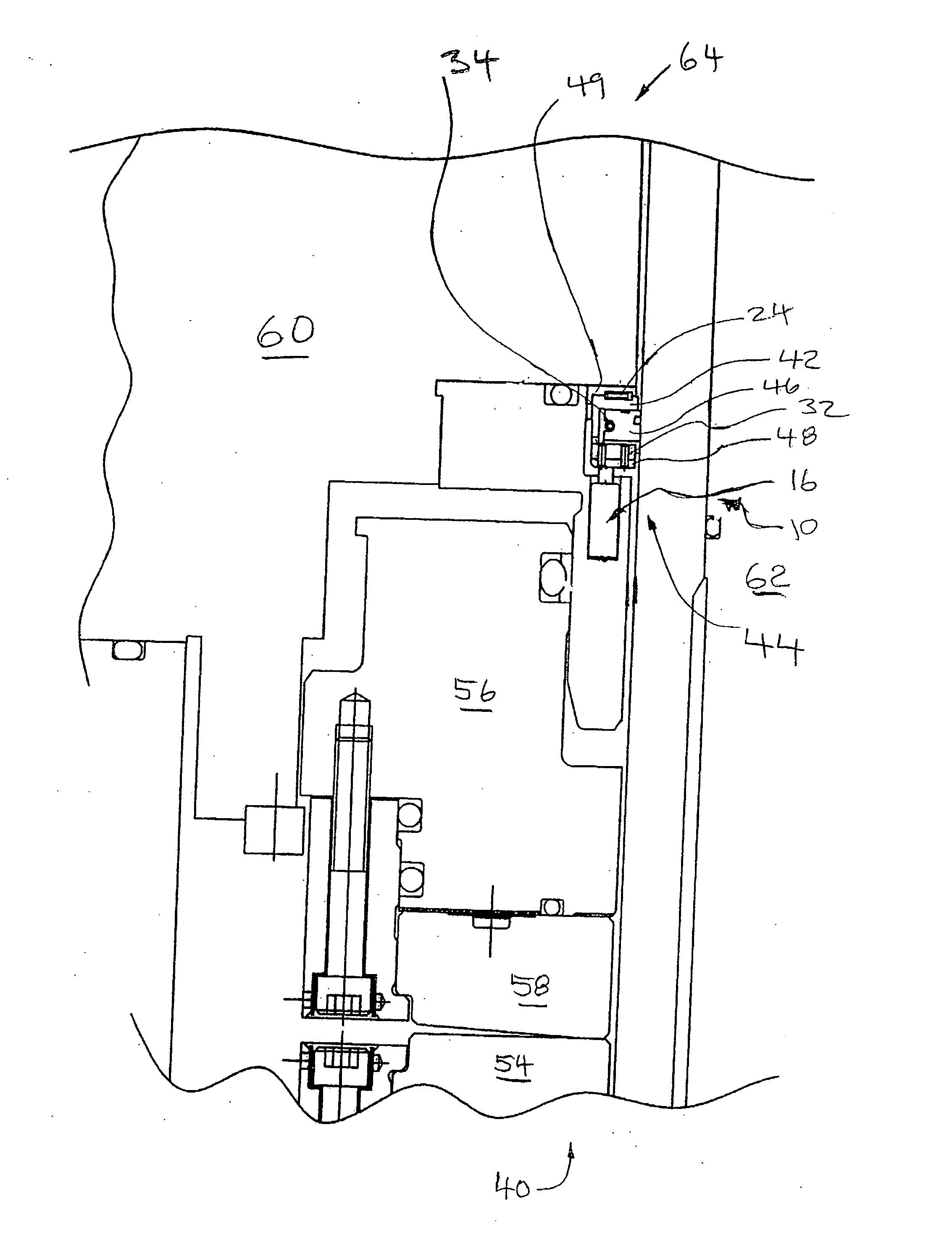
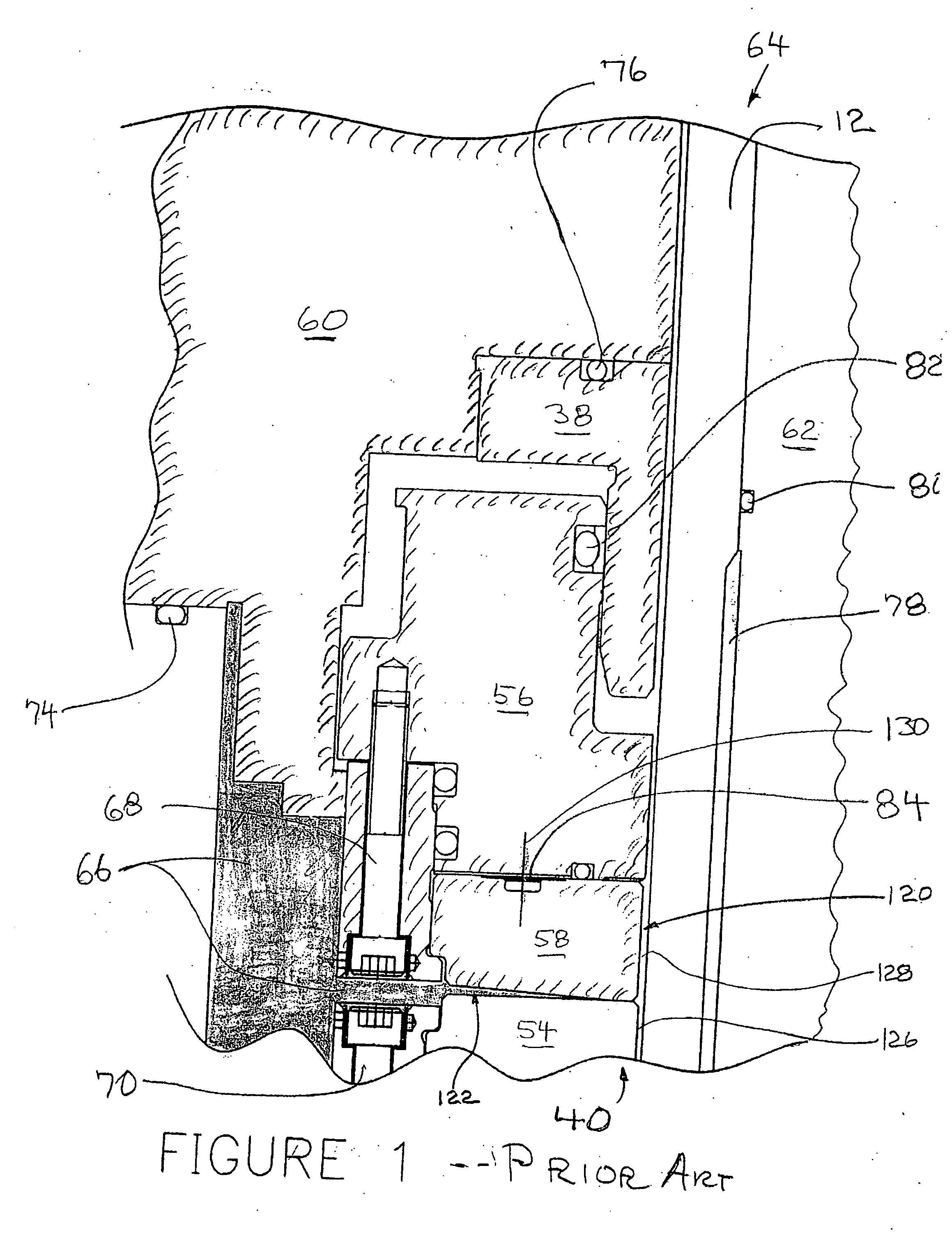
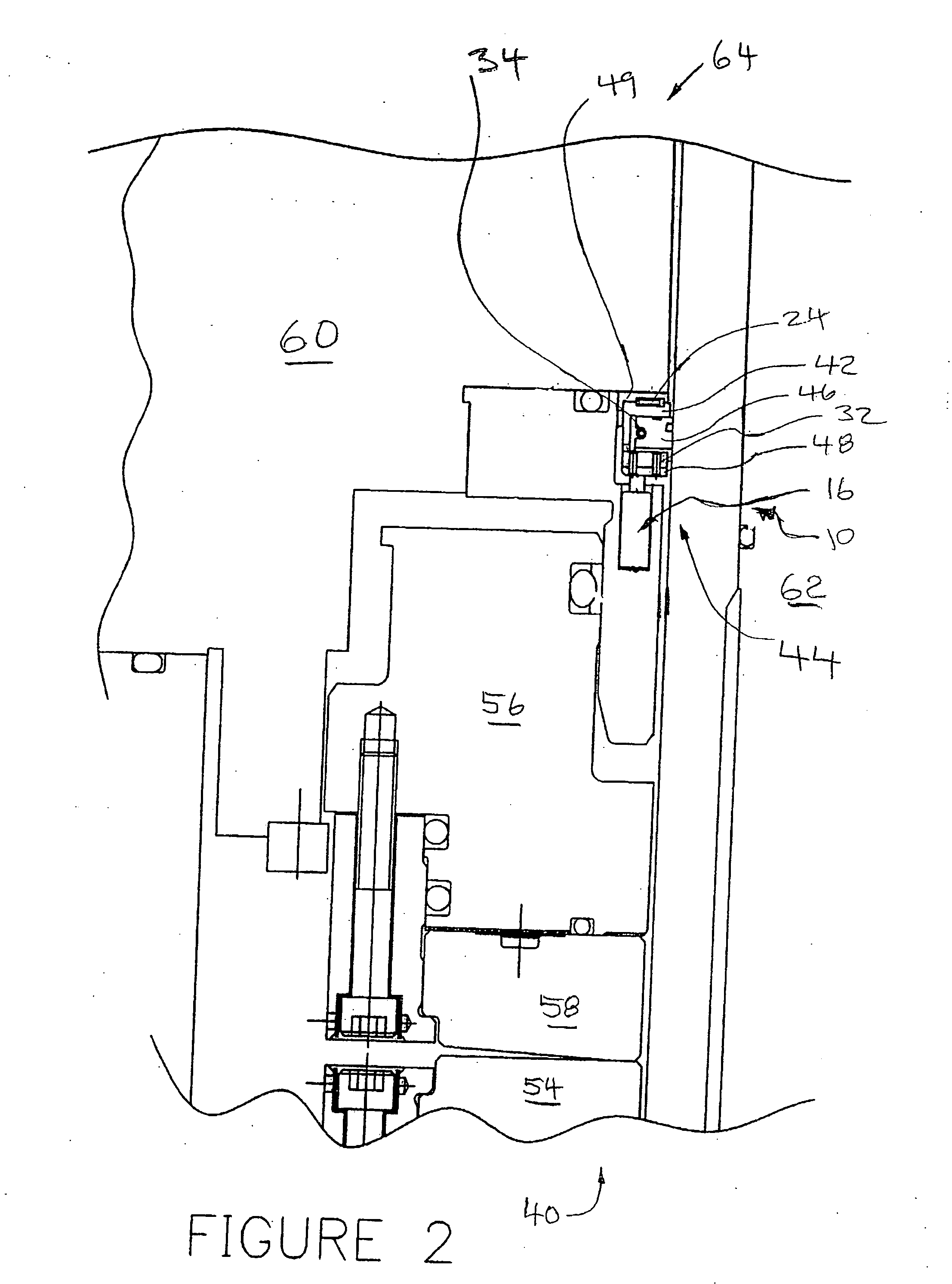
[0050] Referring to the drawings in general and to FIG. 1 in particular, the broken longitudinal section of a portion of a exemplary prior art reactor coolant pump reveals the primary seal assembly of the pump, with the primary seal assembly being designated generally 40 and including a runner faceplate 54 and a ring faceplate 58, with exceedingly small space identified as 122 between these faceplates defining the primary seal. A area filled with high pressure coolant water within the pump during normal operation is denoted generally 66. During normal pump operation coolant water pressure in area 66 may be as high as two thousand two hundred-fifty pounds per square inch (2,250 psi).

[0051] The pump includes a motor rotatably driving a pump shaft 62. The shaft 62 shown in FIG. 1; the motor is not illustrated in FIG. 1 but is normally located at what is, relative to FIG. 1, the lower end of pump shaft 62. Further affixed to pump shaft 62, and driven by pump shaft 62 as pump shaft 62 r...


PUM


Abstract

A thermally actuated shutdown seal provides a shutdown seal usable in a pump having a primary seal assembly positioned circumferentially about a rotating shaft for separating a region of high pressure coolant fluid from the shaft. The shutdown seal includes a two-piece interlocked housing which encompasses carbon graphite ring segments positioned circumferentially about the shaft, a garter spring and a series of compression springs. The replaceable insert with machined recess contains the shutdown seal assembly and is biased axially with a wave spring and held with the annular recess by a closure ring. The seal is designed with coolant fluid flow directly in contact with such ring segments and specially designed paths around the ring segments during normal pump operation. The seal requires a thermally actuated means for moving the two-piece interlocked housing axially into a blocking position within the coolant flow path to shutdown and minimize fluid flow bypassing the ring segments and between the ring segments and the pump shaft, upon occurrence of a process failure in the facility served by the pump and consequent temperature rise of the fluid being pumped.

Description

CROSS REFERENCE TO RELATED PATENT APPLICATION [0001] This patent application claims the benefit, under 35 USC 119, of the filing date of U.S. provisional patent application Ser. No. 60 / 725,471 filed Oct. 11, 2005 in the name of Mark E. Sanville and Reinhold Koeth. The disclosure of the '471 application, entitled “REACTOR COOLANT PUMP SHUTDOWN SEAL”, is hereby incorporated by reference in its entirety.BACKGROUND OF THE INVENTION [0002] 1. Field of the Invention [0003] This invention relates to seals for use in pumps for coolant for nuclear pressurized water reactors in nuclear power plants, in which release of contaminated or toxic fluid, such as radioactive water, must be prevented in the event of a pump malfunction or other equipment failure in the facility. [0004] 2. Description of the Prior Art [0005] Mechanical shaft sealing systems for coolant pumps in nuclear power plants and other nuclear installations have been in commercial service since the 1960s. Such sealing systems typi...

Claims


Application Information

Patent Timeline
IPC IPC(8): F04B17/00
CPCF04D7/08F04D29/146F16J15/008F16J15/164F16J15/38F16J15/442
Inventor SANVILLE, MARK E.KOETH, REINHOLDHOWARD, BRUCE A.MANGERIE, BOB
Owner STEIN SEAL
Why Eureka
Try Eureka