
Robotic surgical system with joint motion controller adapted to reduce instrument tip vibrations

Active Publication Date: 2007-06-21
INTUITIVE SURGICAL OPERATIONS INC
View PDF16 Cites 157 Cited by
  • Summary
  • Abstract
  • Description
  • Claims
  • Application Information

AI Technical Summary

Benefits of technology

[0008]Accordingly, an object of aspects of the present invention is a robotic arm assembly joint controller for reducing vibrations that may otherwise be experienced on a tip of a surgical instrument during a surgical procedure without adding undue delay.
[0009]Another object of aspects of the present invention is a robotic arm assembly joint controller for reducing vibrations that may otherwise be experienced on a tip of a surgical instrument during a surgical procedure, and providing force feedback indicative of forces being asserted against the instrument tip back to a surgeon performing the procedure without jeopardizing control system stability.
[0010]These and additional objects are accomplished by the various aspects of the present invention, wherein briefly stated, one aspect is a robotic surgical system comprising: a surgical instrument; a robotic arm assembly holding the surgical instrument; a master manipulator; and a controller configured to control movement of the surgical instrument in response to user operation of the master manipulator in such a manner that vibrations experienced at a tip of the surgical instrument are reduced by filtering an output of the master manipulator that may induce the vibrations while at least partially compensating in a feedback path back to the master manipulator for delay induced by such filtering so as to enhance stability of such control.
[0011]Another aspect is a control system included in a controller for controlling movement of a robotic arm assembly in response to user manipulation of a master manipulator, wherein the control system controls rotation of a slave joint of the robotic arm assembly. The control system comprises: a filter in a forward control path defined as being from the master manipulator to a motor coupled to the slave joint, wherein the filter attenuates frequency content of a joint position command generated from user manipulation of the master manipulator so that vibrations experienced at a tip of a surgical instrument held by the robotic arm assembly are reduced; and an inverse filter in a feedback path defined as being from a slave joint sensor to the master manipulator, wherein the slave joint sensor senses movement of the slave joint and the inverse filter provides a phase lead in the feedback path so as to at least partially compensate for a phase lag caused by the filter.
[0012]Another aspect is a method for controlling the movement of a slave joint in a robotic arm assembly, comprising: generating filtered position, velocity and acceleration slave joint commands so as to command movement of the slave joint while reducing vibrations experienced on a tip of a surgical instrument held by the robotic arm assembly; generating a motor command signal using the filtered position, velocity and acceleration slave joint commands; providing the motor command signal to a motor coupled to the slave joint; receiving sensed positions of the slave joint; generating estimated positions, velocities and accelerations of the slave joint using the sensed positions of the joint and the motor command signal; and updating the motor command signal using a function of the differences between the filtered position, velocity and acceleration slave joint commands and the estimated positions, velocities and accelerations of the slave joint.
[0013]Still another aspect is a method for reducing vibrations on a tip of a surgical instrument held by a robotic arm assembly without degrading stability of a control system controllably moving a slave joint of the robotic arm assembly. The method comprises: attenuating a first signal indicating slave joint position commands generated from user manipulation of a master manipulator at frequencies beyond a cut-off frequency so that vibrations on the tip of the surgical instrument held by the robotic arm assembly are reduced at those frequencies; and amplifying a second signal indicating a position of the slave joint at frequencies above the cut-off frequency while providing phase lead to the second signal so as to at least partially compensate for delay caused by the attenuation of the first signal and stably generate a feedback signal provided to the master manipulation.

Problems solved by technology

While performing a surgical procedure, vibrations experienced on a tip of a surgical instrument may cause control problems for a surgeon.
For example, such vibrations may make it difficult for the surgeon to perform fine surgical manipulations of tissue, needles and sutures.
A flexible robotic arm assembly, especially when mounted on flexible setup arms and / or with unbalanced link masses and inertias, may cause such vibrations to easily get started by fast transient motions commanded by the surgeon on a master manipulator.
In addition, vibrations may also occur as a result of any non-smooth command motion of the master manipulator.
Although a low pass filter may be employed in a teleoperation control system to filter out master manipulator motion commands that may cause vibration occurring at frequencies above those of intended surgical motion, such a low pass filter also inserts delay into the teleoperation system, specifically between the master commanded motion and the actual robotic arm assembly motion.
Unfortunately, when force feedback indicative of forces being asserted against the tip of the surgical instrument is provided back to the surgeon through the master manipulator, the delay added to the teleoperation control system by the low pass filter tends to drive the control system unstable.
This greatly limits either the ability to filter out undesirable vibrations or the ability of the system to provide the surgeon with haptic force feedback.

Method used


Image

  • Robotic surgical system with joint motion controller adapted to reduce instrument tip vibrations
  • Robotic surgical system with joint motion controller adapted to reduce instrument tip vibrations
  • Robotic surgical system with joint motion controller adapted to reduce instrument tip vibrations

Examples


Embodiment Construction

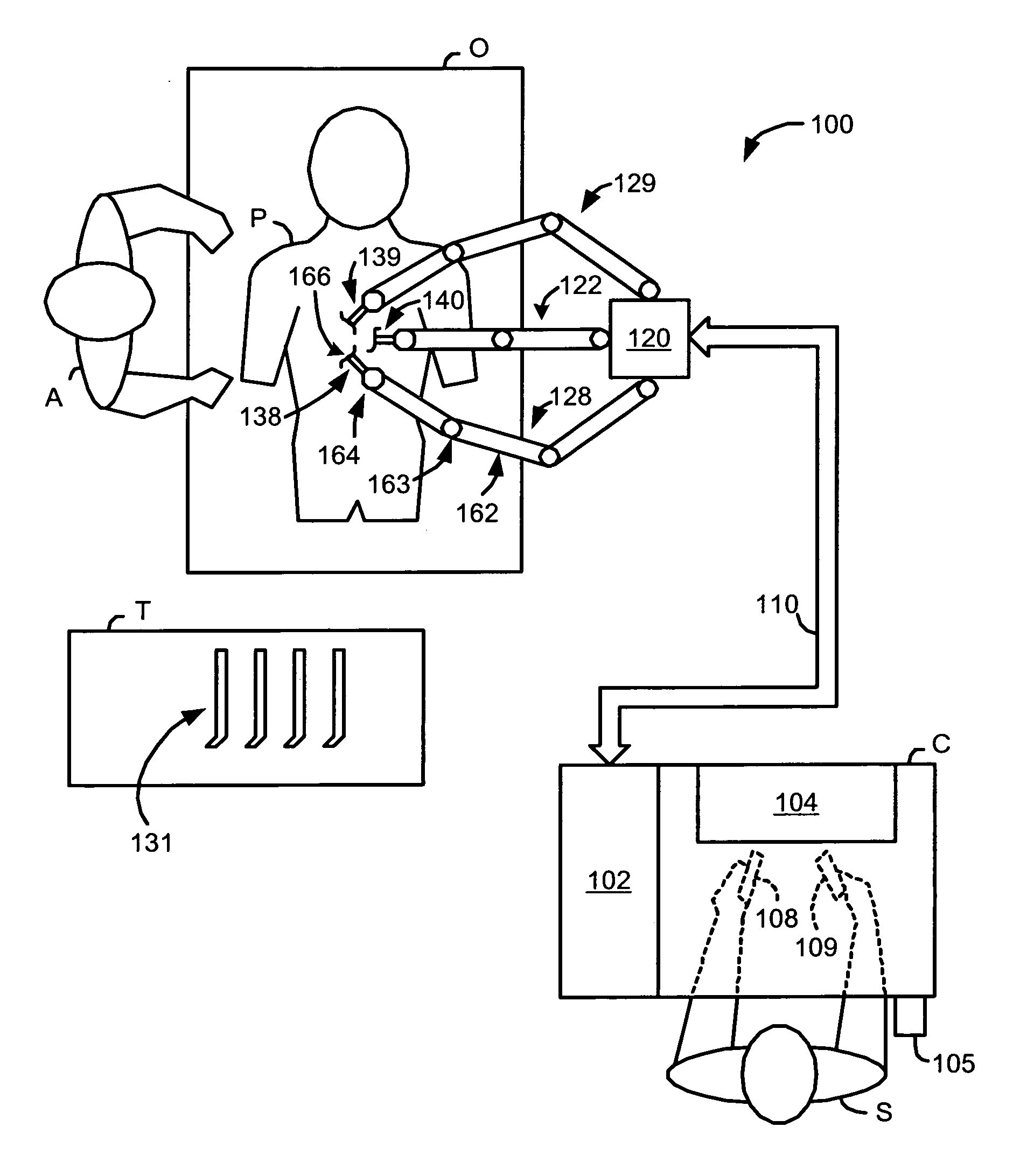
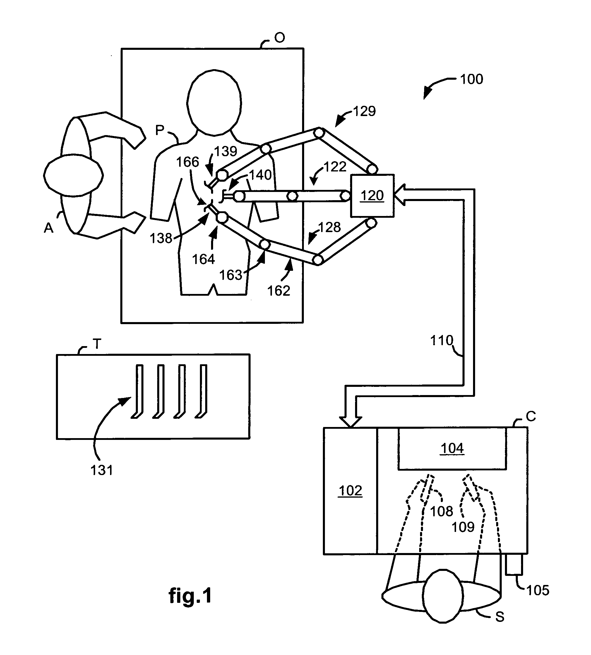
[0029]FIG. 1 illustrates, as an example, a top view of an operating room employing a robotic surgical system. The robotic surgical system in this case is a robotic surgical system 100 including a Console (“C”) utilized by a Surgeon (“S”) while performing a minimally invasive diagnostic or surgical procedure, usually with assistance from one or more Assistants (“A”), on a Patient (“P”) who is lying down on an Operating table (“O”).

[0030]The Console includes a monitor 104 for displaying an image of a surgical site to the Surgeon, left and right manipulatable control devices 108 and 109, a foot pedal 105, and a processor 102. The control devices 108 and 109 may include any one or more of a variety of input devices such as joysticks, gloves, trigger-guns, hand-operated controllers, or the like. The processor 102 is preferably a dedicated computer that may be integrated into the Console or positioned next to it.

[0031]The Surgeon performs a minimally invasive surgical procedure by manipul...


PUM


Abstract

A robotic surgical system has a robot arm holding an instrument for performing a surgical procedure, and a control system for controlling movement of the arm and its instrument according to user manipulation of a master manipulator. The control system includes a filter in its forward path to attenuate master input commands that may cause instrument tip vibrations, and an inverse filter in a feedback path to the master manipulator configured so as to compensate for delay introduced by the forward path filter. To enhance control, master command and slave joint observers are also inserted in the control system to estimate slave joint position, velocity and acceleration commands using received slave joint position commands and torque feedbacks, and estimate actual slave joint positions, velocities and accelerations using sensed slave joint positions and commanded slave joint motor torques.

Description

CROSS REFERENCE TO RELATED APPLICATIONS[0001]This application claims priority to U.S. provisional application Ser. No. 60 / 751,947 filed Dec. 20, 2005, which is incorporated herein by reference.FIELD OF THE INVENTION[0002]The present invention generally relates to robotic surgical systems and in particular, to a robotic surgical system with joint motion controller adapted to reduce surgical instrument tip vibrations without significantly degrading control system stability.BACKGROUND OF THE INVENTION[0003]Robotic surgical systems such as those used in performing minimally invasive surgical procedures offer many benefits over traditional open surgery techniques, including less pain, shorter hospital stays, quicker return to normal activities, minimal scarring, reduced recovery time, and less injury to tissue. Consequently, demand for minimally invasive surgery using robotic surgical systems is strong and growing.[0004]One example of a robotic surgical system is the da Vinci® Surgical S...

Claims


Application Information

Patent Timeline
IPC IPC(8): G06F19/00
CPCA61B1/00193A61B1/313A61B19/22A61B2019/2288B25J9/1689G05B2219/39241G05B2219/40144G05B2219/40406G05B2219/45117G06F19/3406G06F19/3418G06F19/3481A61B34/70A61B34/75G16H20/40G16H40/63
Inventor PRISCO, GIUSEPPEROSA, DAVID J.
Owner INTUITIVE SURGICAL OPERATIONS INC
Learn More