Scanning probe apparatus and drive stage therefor

Inactive Publication Date: 2007-06-28
CANON KK
View PDF8 Cites 4 Cited by
  • Summary
  • Abstract
  • Description
  • Claims
  • Application Information

AI Technical Summary

Benefits of technology

[0027] According to an embodiment of the present invention, it is possible to ensure a movable range of the movable portion as a counterweight, so that an inert

Problems solved by technology

In the above described cases, a movable range of the inner cylindrical piezoelectric element and the counterweight is further restricted, so that there is a possibility that th

Method used


Image

  • Scanning probe apparatus and drive stage therefor
  • Scanning probe apparatus and drive stage therefor
  • Scanning probe apparatus and drive stage therefor

Examples


Example

Embodiment 1

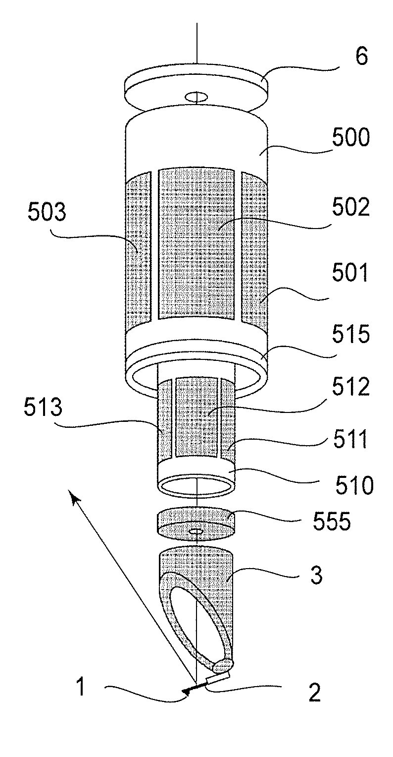
[0049]FIG. 1 is a schematic view for illustrating constitutional parts of a drive stage of a scanning probe apparatus in this embodiment of the present invention. FIG. 2 is a schematic sectional view of the drive stage.

[0050] In this embodiment, the drive stage is used as a drive stage for a probe, not for a sample.

[0051] Onto a base table 505 as a sample holding table having a throughhole through which light passes, a cantilever holding member 3 for holding a cantilever 2 having a probe 1 is connected.

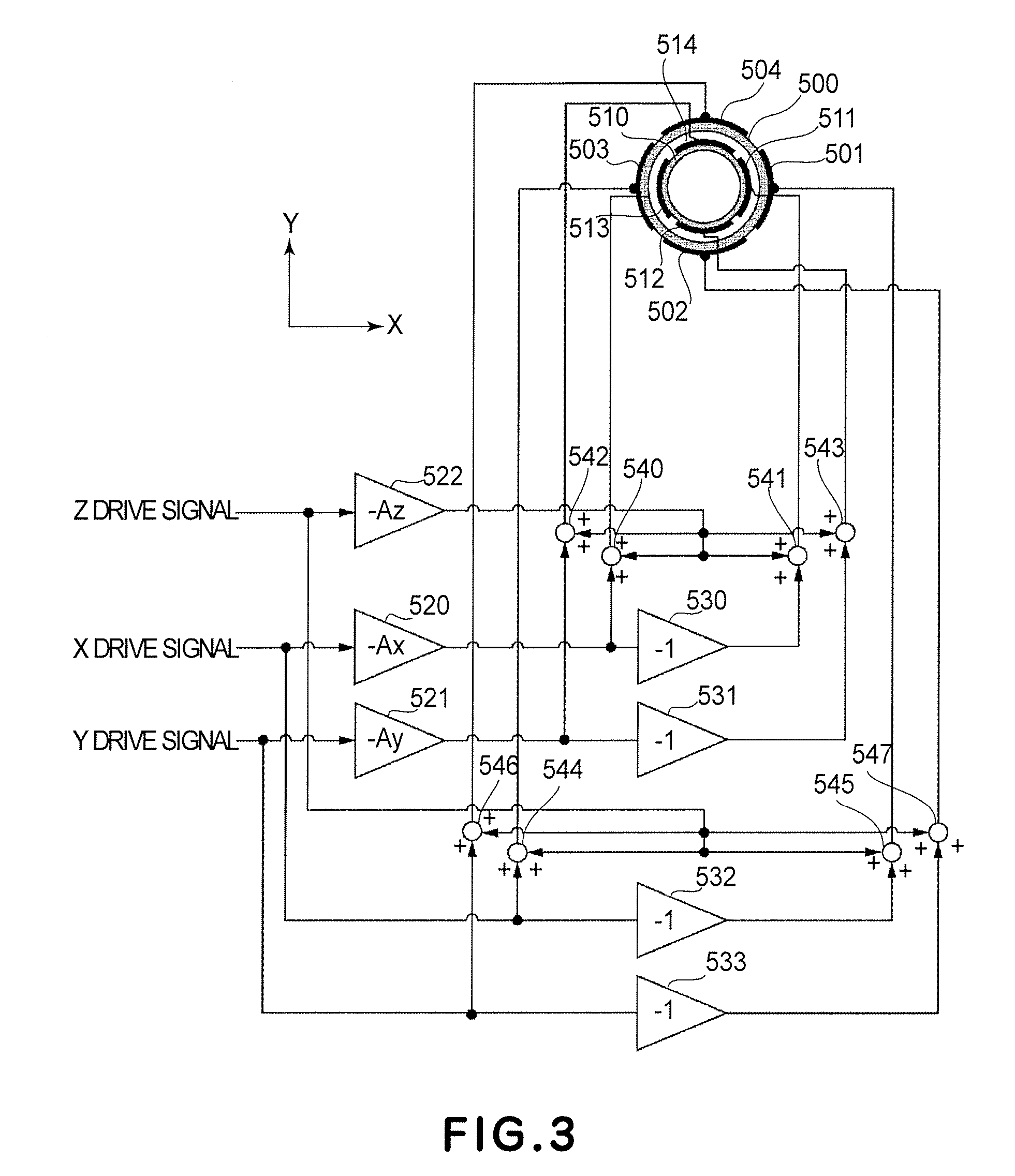
[0052]FIG. 3 is a schematic view for illustrating a driving method of the drive stage of this embodiment.

[0053] As shown in FIG. 3, the drive stage includes two drive elements consisting of two cylindrical piezoelectric elements concentrically disposed. More specifically, inside a first cylindrical piezoelectric element 500, a second cylindrical piezoelectric element 510 is concentrically disposed. This state is shown in FIG. 1 as an exploded view. Around the first cy...

Example

Embodiment 2

[0060]FIG. 4 is a schematic view for illustrating constituting parts of a drive stage for a scanning probe apparatus in this embodiment.

[0061] A structure and operation of two drive elements consisting of two cylindrical piezoelectric elements are identical to those in Embodiment 1.

[0062] On a supporting member 6, a small-diameter cylindrical piezoelectric element as a drive element 510 is fixed. At an end portion of the drive element 510 for a sample holding table, a probe table or sample holding table 505 formed of a light-transmissive substance is provided. The table 505 may also be provided with a hollow central portion. The table 505 is configured to hold a probe as the probe table or a sample as the sample holding table.

[0063] The drive element 510 is provided with a plurality of elements 511, 512 and 513 so that scanning drive of the sample can be effected by applying a voltage between opposite electrodes to displace the cylindrical piezoelectric element is de...

Example

Embodiment 3

[0074]FIG. 5 shows an atomic force microscope (AFM) as the SPM according to this embodiment of the present invention.

[0075] Referring to FIG. 5, the AFM includes a frame 10 of a main assembly of apparatus, a recess portion 11 of the apparatus main assembly provided with a visible light source for sample observation and an image sensor, a scanning stage (drive stage) 12 for performing scanning of sample, a sample 13 which is an object to be observed or processed, a recess portion 14 provided with a light source for a drive stage of the apparatus main assembly, a scanning stage (drive stage) 15 for performing scanning of a probe 17, and a cantilever 16 provided with the probe 17. A reference numeral 18 represents a drive control circuit including a drive circuit, a control circuit, a detection circuit, and an image processing circuit. A light-receiving portion for receiving reflected light for measuring displacement of the probe 17 is not shown since it can be constitute...


PUM


Abstract

A drive stage, for driving a sample or a probe, capable of ensuring a movable range of a movable portion as a counterweight and always effectively canceling an inertial force to suppress vibration of a supporting member leading to vibration of the sample or the probe includes a counter drive element for moving the probe or a sample holding table and a movable portion movable in a direction in which the inertial force generated during movement of the probe or the sample holding table. The movable portion surrounds the counter drive element outside the counter drive element.

Description

FIELD OF THE INVENTION AND RELATED ART [0001] The present invention relates to a scanning probe apparatus for obtaining information of a sample or effecting processing of the sample or information recording by ordinarily utilizing a scanning probe microscope (SPM), and a drive stage for the scanning probe apparatus. [0002] Japanese Laid-Open Patent Application (JP-A) No. 2002-082036 has disclosed a scanning mechanism for an SPM capable of suppressing an occurrence of a vibration caused by a scanning operation to permit high-accuracy position control at high speed. [0003] More specifically, as shown in FIG. 6, a scanning mechanism 200 includes bases 201 and 202 for drive elements (actuators), drive element holding member 206 and 207 provided on the bases, a drive element 203 held by these holding members and capable of expanding and contracting in Y direction, a drive element 204 fixed at one end of the drive element 203 and capable of expanding and contracting in X direction, a driv...

Claims


Application Information

Patent Timeline
IPC IPC(8): G12B21/24G01N13/10G01Q20/02G01B21/30G01Q10/04G01Q30/00G01Q60/00
CPCB82Y35/00G01Q70/04G01Q10/02
Inventor YOSHIMATSU, NOBUKIKUSAKA, TAKAOYASUDA, SUSUMUSEKI, JUNICHI
Owner CANON KK
Why Eureka
Try Eureka