Method and apparatus for shock wave mitigation

a technology of shock wave and apparatus, applied in the direction of shields, reactive armour, transportation and packaging, etc., can solve the problems of ineffective blast wave impact, destroying vehicles, incapacitate personnel, and thousands of deaths of military personnel, and achieve the effect of reducing the impact of blast wav

Inactive Publication Date: 2007-06-28
BOARD OF RGT UNIV OF NEBRASKA
View PDF25 Cites 23 Cited by
  • Summary
  • Abstract
  • Description
  • Claims
  • Application Information

AI Technical Summary

Benefits of technology

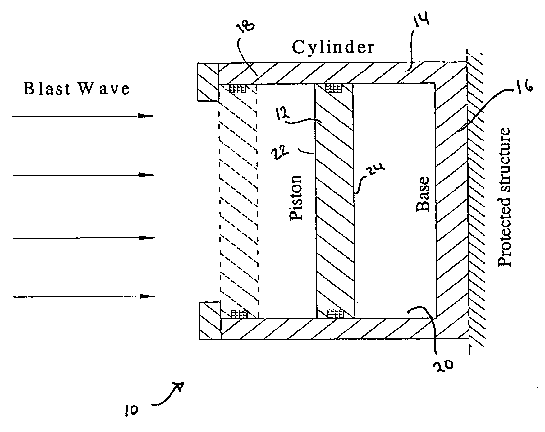
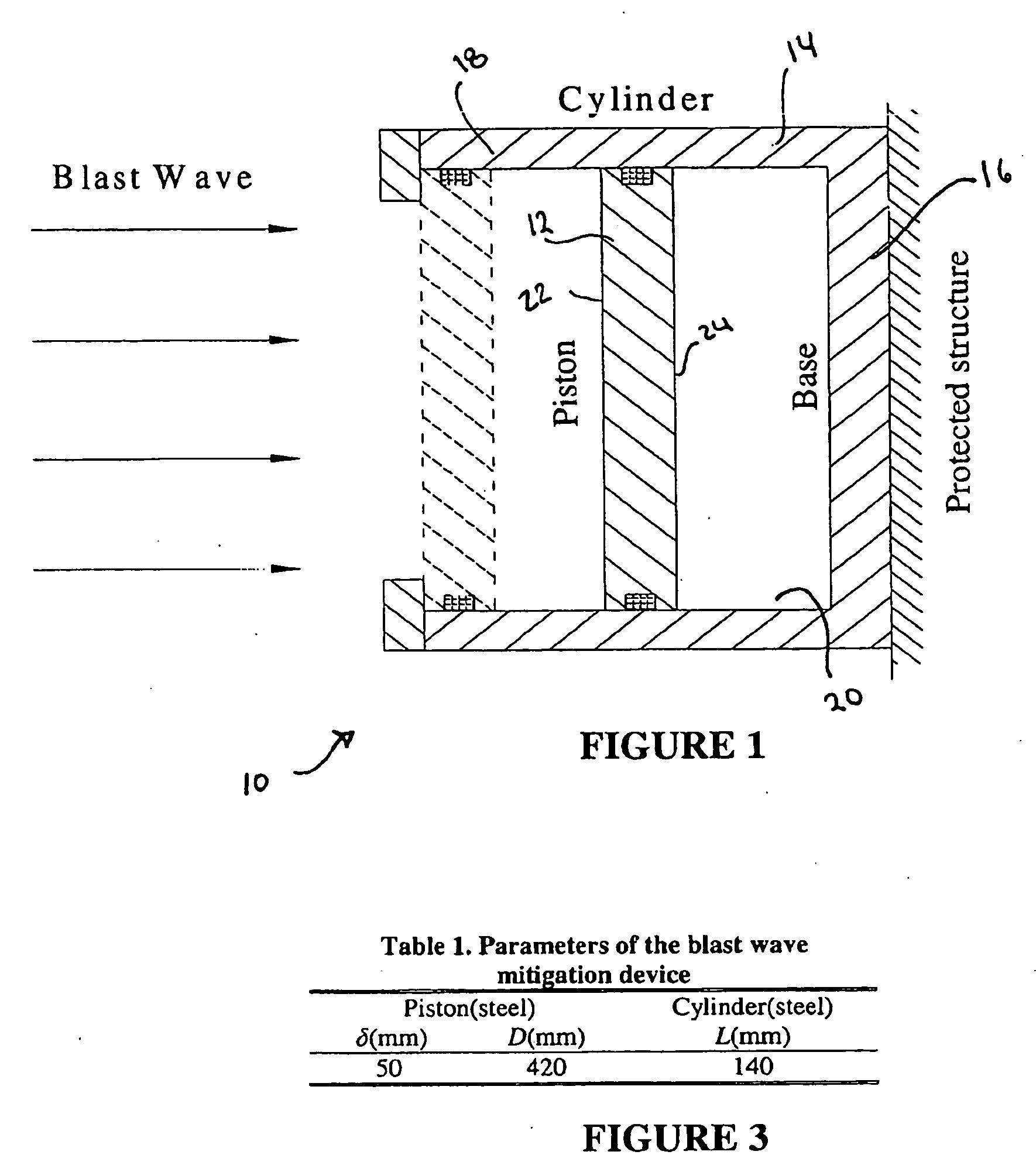
[0012] The present invention generally relates to an assembly for mitigating a blast compression wave. The assembly comprises a housing having a base wall, an outwardly extending wall, and an open end. A piston having an impact face and an interior face is slidably received in the housing in a substantially airtight engagement therewith. The piston, the base wall and the outwardly extending wall define an interior. A compressible substance is confined within the interior, whereby when the blast wave impacts the impact face of the piston and drives the piston toward the base of the housing, a shock wave is induced in the compressible substance. The shock wave is reflected by the base of the enclosure and the interior surface of the piston to mitigate the impact of the blast wave.

Problems solved by technology

Conflicts throughout the World have already caused thousands of deaths of military personnel.
Explosion of land mines and IEDs send out blast waves of extremely high pressures, which destroy vehicles and incapacitate personnel.
While hardening may be effective against projectiles, it is not effective against blast wave impacts.
The blast wave easily propagates through the hardened armor with little mitigation, killing occupants and damaging equipment.
For aqueous foams, the vaporization of the liquid component has been shown to be detrimental to blast wave mitigation.
Specifically, the many reflections off the foam / air interface produce a complicated waveform in the aqueous foam.
For the high blast wave pressure, the cellular material will be destroyed and the pressure on the target will increase with adverse impact.
In spite of their successful application to date, current methods and systems for using aqueous foams in pressure attenuating roles are inefficient and unnecessarily bulky.
Blast walls are typically massive and are thus inherently immobile and expensive.
They cannot, therefore, be used in the majority of mobile applications.

Method used


Image

  • Method and apparatus for shock wave mitigation
  • Method and apparatus for shock wave mitigation
  • Method and apparatus for shock wave mitigation

Examples


example

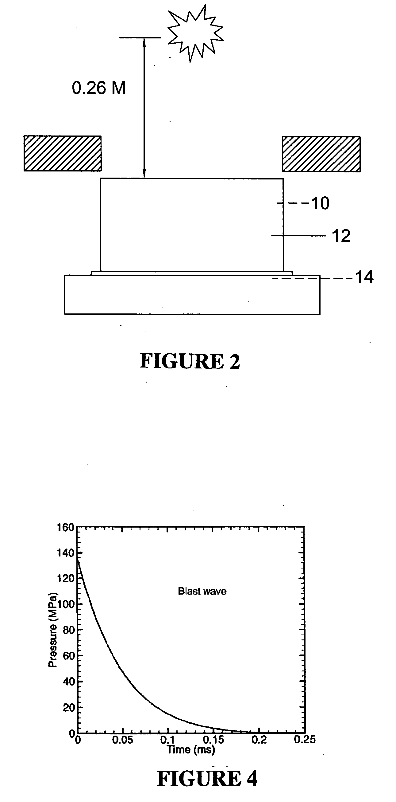
[0027] In an effort to determine the effectiveness of the blast mitigation device 10 of the present invention, the blast mitigation device was setup as shown in FIG. 2. A honeycomb structure, which can withstand a peak pressure of about 2 MPa, is placed on a steel test platform. The honeycomb structure was covered by either the blast wave mitigation device 10 of the present invention or a control device. The control device has the same dimensions and weight as the blast wave mitigation device. A rolled homogeneous armor steel plate is used to protect the honeycomb structure that is not covered by the blast wave mitigation and control device 10. A hole was cut at the center of the steel plate to expose the blast wave mitigation device and control device. The diameter of the hole is the same as that of the blast wave mitigation device. The steel plate has a thickness of approximately 9 cm. The blast wave is generated by detonating 1.36 kg of Pentolite at a distance of 0.26 m. This set...


PUM


Abstract

A method and apparatus for mitigating blast compression waves is disclosed. The apparatus has a housing having an open end, and a piston slidably received in the open end of the housing in a substantially airtight engagement therewith. The piston and the housing define an interior wherein a compressible substance is confined. When a blast wave impacts the impact face of the piston and drives the piston toward the base of the housing, a shock wave is induced in the compressible substance. The shock wave is reflected by the base of the enclosure and the interior surface of the piston to mitigate the impact of the blast wave.

Description

CROSS-REFERENCE TO RELATED APPLICATIONS [0001] This application claims priority to commonly owned U.S. provisional application Ser. No. 60 / 721,798, filed Sep. 29, 2005, which is incorporated by reference in its entirety.STATEMENT REGARDING FEDERALLY SPONSORED RESEARCH OR DEVELOPMENT [0002] This invention was made with government support under grants from the U.S. Army Research Office, Contract number W911NF-04-2-0011. The government does not have any rights in this invention.TECHNICAL FIELD [0003] The present invention relates generally to methods and apparatus for pressure wave mitigation and, more specifically, to methods and apparatus for blast wave mitigation. BACKGROUND OF THE INVENTION [0004] Conflicts throughout the World have already caused thousands of deaths of military personnel. A large percentage of these deaths are due to land mines and improvised explosive devices (IEDs). Explosion of land mines and IEDs send out blast waves of extremely high pressures, which destroy ...

Claims


Application Information

Patent Timeline
Patent Type & Authority Applications(United States)
IPC IPC(8): F41H13/00
CPCF41H5/007F42D5/045
Inventor ZHANG, ZHAOYANGOGOS, GEORGE
Owner BOARD OF RGT UNIV OF NEBRASKA
Why Eureka
Try Eureka