
Ballast integrated circuit (IC)

a technology of integrated circuits and ballasts, applied in the field of ballast integrated circuits, can solve the problems of high emi, high level of ic, and ic may be operated erroneously

Active Publication Date: 2007-06-28
SEMICON COMPONENTS IND LLC
View PDF7 Cites 16 Cited by
  • Summary
  • Abstract
  • Description
  • Claims
  • Application Information

AI Technical Summary

Benefits of technology

[0035] In some embodiments, the mode detector, if the voltage of the second input terminal is equal to or higher than a predetermined magnitude, recognizes a dead-time control mode, generates the enable signal, stops operation of the preheating/ignition controller, and activates operations of the active zero-voltage switching controller.
[0036] In some embodiments, the ballast integrated circuit (IC) further comprises: an under voltage lock-out (UVLO) unit for transmitting a reset signal to the mode detector if a power-supply voltage is equal to or less than a predetermined magnitude required for normal operations, the...

Problems solved by technology

In this case, the conduction loss is high, and an abrupt current flow occurs in the switch, resulting in a high level of EMI.
Also, the IC may be operated erroneously.
These can generate a high-frequency noise in the IC, such that the IC may be erroneously operated.
However, if the dead time is not properly adjusted according to load states, the zero-voltage switching may be incorrectly performed.
If a faulty- or erroneous-operation occurs, the system may not be protected from danger and harm, making it is impossible to guarantee the stability of the system.

Method used


Image

  • Ballast integrated circuit (IC)
  • Ballast integrated circuit (IC)
  • Ballast integrated circuit (IC)

Examples


Embodiment Construction

[0055] The present invention will be described in detail with reference to the annexed drawings. In the drawings, the same or similar elements are denoted by the same reference numerals. In the following description, a detailed description of known functions and configurations incorporated herein will be omitted for clairity.

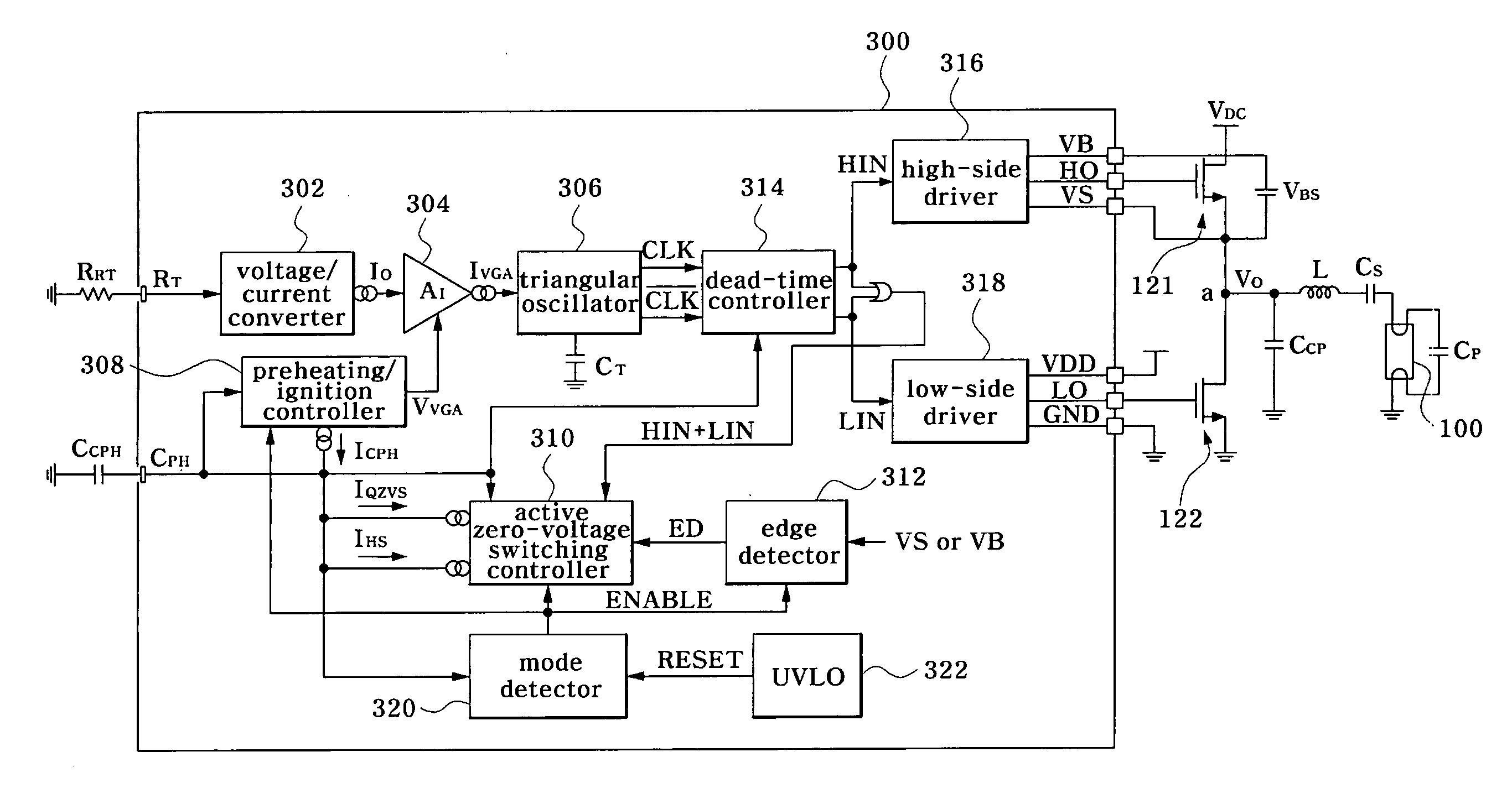
[0056]FIG. 5 is a circuit diagram illustrating a ballast IC 300. In some embodiments, the ballast IC 300 includes two input terminals RT and CPH, and six output terminals: VB, HO, VS, VDD, LO, and GND. The ballast IC 300 includes a voltage / current converter (also called a “V / I converter”) 302, a variable gain amplifier (VGA) 304, a triangular oscillator (also called a saw-tooth oscillator) 306, a preheating / ignition controller 308, an active zero-voltage switching controller 310, an edge detector 312, a dead-time controller 314, a high-side driver 316, a low-side driver 318, a mode detector 320, and a UVLO (Under Voltage Lock-Out) unit 322.

[0057] The voltage / c...


PUM


Abstract

A ballast integrated circuit (IC) for driving a first switching element and a second switching element includes: a variable gain amplifier (VGA) connected to a first input terminal connected to a resistor, for generating an output current signal according to a resistance value of the resistor and a gain control signal; a preheating / ignition controller connected to a second input terminal connected to a capacitor, for generating an output current signal and an output voltage signal acting as the gain control signal according to a voltage of the second input terminal; an active zero-voltage controller for generating a hard-switching current signal and an active zero-voltage switching current signal, such that it adjusts the voltage of the second input terminal according to switching states of the first switching element and the second switching element; an oscillator for generating an oscillation signal upon receiving the output current signal from the variable gain amplifier (VGA); and a dead-time controller for receiving the voltage signal of the second input terminal and an output signal of the oscillator, adjusting a dead time using the received signals, and at the same time generating driving signals of the first and second switching elements.

Description

CROSS REFERENCE TO RELATED APPLICATION [0001] This application claims the benefit of Korean Patent Application No. 10-2005-117245, filed on Dec. 2, 2005, in the Korean Intellectual Property Office, the disclosure of which is incorporated herein in its entirety by reference. BACKGROUND OF THE INVENTION [0002] 1. Field of Invention [0003] The present invention relates to a ballast integrated circuit (IC), and more particularly to a ballast IC for automatically adjusting a dead time according to load characteristics. [0004] 2. Description of Related Art [0005]FIG. 1 is a circuit diagram illustrating a fluorescent-lamp driving circuit including a conventional ballast IC. FIG. 2 is a graph illustrating operations of the ballast IC of FIG. 1. In FIG. 2, a horizontal axis indicates a frequency, and a vertical axis indicates a magnitude. [0006] The inverter circuit for driving the fluorescent lamp 100 includes first and second switching elements 121 and 122 operated by ballast IC 110. The f...

Claims


Application Information

Patent Timeline
IPC IPC(8): H05B41/36
CPCH05B41/2981H05B41/2985H05B41/2986H05B41/14
Inventor HWANG, JONG-TAEKIM, DAE-HOJUNG, MOON-SANGKIM, DONG-HWAN
Owner SEMICON COMPONENTS IND LLC
Learn More