Eureka AIR delivers breakthrough ideas for toughest innovation challenges, trusted by R&D personnel around the world.

Active filer circuit for limiting band of input signal

Inactive Publication Date: 2007-06-28
SANYO ELECTRIC CO LTD
View PDF2 Cites 2 Cited by
  • Summary
  • Abstract
  • Description
  • Claims
  • Application Information

AI Technical Summary

Benefits of technology

[0008] In this instance, the “active elements” may include transistors. Examples thereof include a transconductance amplifier which consists of a plurality of transistors. The “plurality of capacitive elements formed on the outputs of the respective plurality of active elements” may refer to such an arrangement where the capacitive elements are connected to the output ends of the respective active elements. The capacitive elements may be arranged between the output ends of the active elements and earth (ground). The “active element to which the output of the active element in the final stage is input” may include a transistor that serves as a load capacitance to the active element in the final stage. The “device areas of the active elements” include, for example, the gate areas of the input terminals of transconductance amplifiers. According to this embodiment, the areas of the gate capacitances and the ratios of the capacitances of the respective filters are made constant with respect to each other. This makes it possible to keep the capacitances, including the parasitic capacitances, of the capacitive elements constant.

Problems solved by technology

This makes it difficult to achieve the desired filter characteristics with stability.

Method used


Image

  • Active filer circuit for limiting band of input signal
  • Active filer circuit for limiting band of input signal
  • Active filer circuit for limiting band of input signal

Examples


Embodiment Construction

[0020] The invention will now be described by reference to the preferred embodiments. This does not intend to limit the scope of the present invention, but to exemplify the invention.

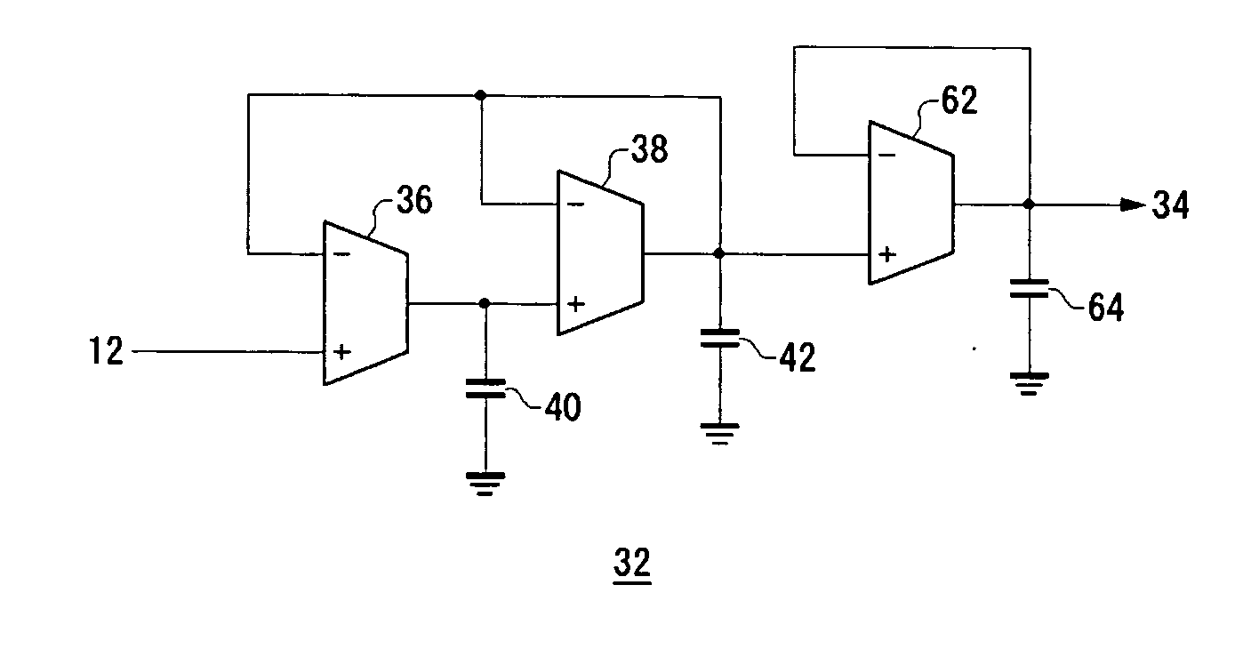
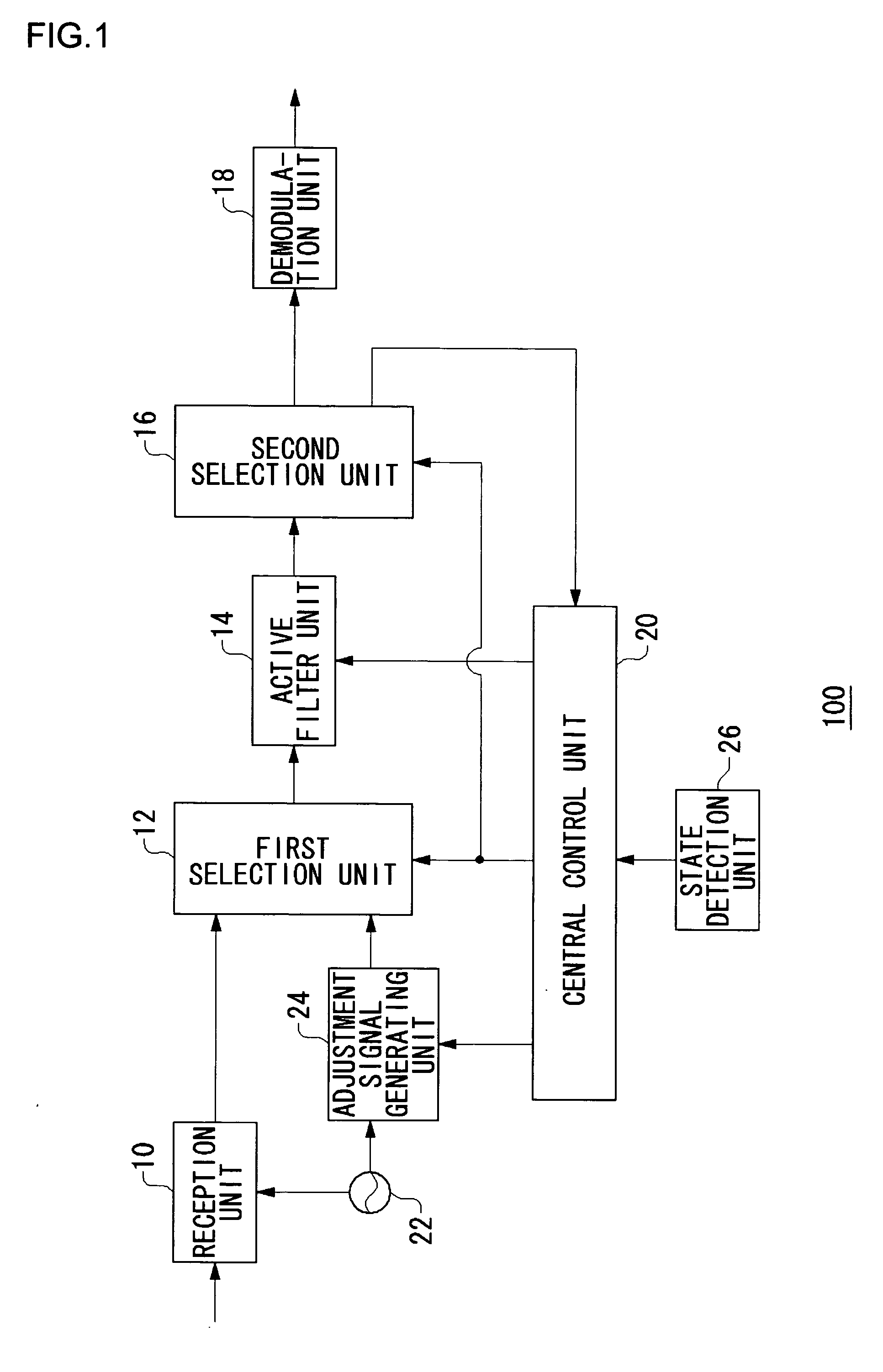
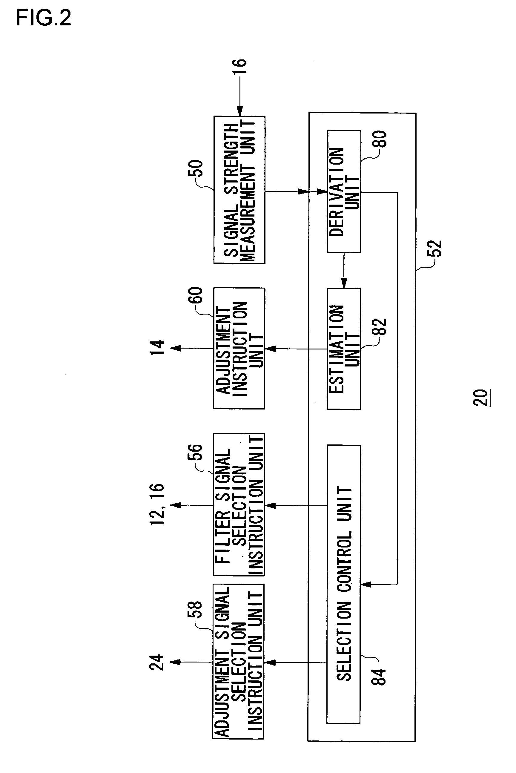
[0021] Before describing the embodiment in detail, the present invention will initially be overviewed. A communication apparatus 100 according to the embodiment of the present invention has a filter circuit which can actively adjust its filter characteristics. To “actively adjust” includes, for example, adjusting the filter characteristics automatically when the communication apparatus is powered on and when a change occurs in the use environment of the communication apparatus, or the temperature environment in particular. When adjusting the filter characteristics, a plurality of adjustment signals generated by a PLL (Phase-Locked Loop) are initially switched in turn to measure the attenuations of their respective signal strengths, and to calculate differences therebetween. Then, the cutoff frequency o...


PUM


Abstract

A general purpose of the present invention is to stabilize a filter circuit to desired characteristics without increasing its circuit scale. An active filter unit includes a current control unit, a first gm-C filter unit, and a subsequent circuit. Using a signal output from a central control unit as an input, the current control unit outputs adjustment currents for adjusting gm values, corresponding to respective transconductance amplifiers, to the first gm-C filter unit. The subsequent circuit includes a load capacitance which is composed of an active element such as a transconductance amplifier. The first gm-C filter unit includes the plurality of transconductance amplifiers and a control unit which controls the gm values of the transconductance amplifiers. It limits the band of the signal output from a first filter signal selection unit, and outputs the result to the subsequent circuit.

Description

BACKGROUND OF THE INVENTION [0001] 1. Field of the Invention [0002] The present invention relates to an analog circuit technology, and in particular to a filter circuit which limits a band of an input signal. [0003] 2. Description of the Related Art [0004] Gm-C filters have excellent high-frequency and wide-band filter characteristics, and have recently been used as baseband filters to be mounted on communication apparatuses. A gm-C filter is composed of gm (hereinafter, also referred to as transconductance or transfer conductance) amplifiers and capacitive elements, and its filter characteristics are determined by the ratios between the gains of the gm amplifiers (hereinafter, referred to as gm values) and the capacitances. Due to significant variations in manufacturing, it has been necessary to control the gm values of the gm amplifiers in order to achieve filter characteristics with high precision. To address this problem, the gm values of the gm amplifiers have conventionally be...

Claims


Application Information

Patent Timeline
IPC IPC(8): H03K5/00
CPCH03H11/04H03H11/1252H03H11/1291
Inventor OTSUKA, TAKESHIBANBA, SEIICHI
Owner SANYO ELECTRIC CO LTD
Why Eureka
Eureka Blog
Learn More