
Materials for use in electrophoretic displays

a technology of electrophoretic media and materials, applied in the direction of instruments, door/window protective devices, constructions, etc., can solve the problems of inadequate service life of electrophoretic media, preventing widespread use, and gas-based electrophoretic media being susceptible to the same types of problems

Inactive Publication Date: 2007-06-28
E INK CORPORATION
View PDF1 Cites 72 Cited by
  • Summary
  • Abstract
  • Description
  • Claims
  • Application Information

AI Technical Summary

Problems solved by technology

Nevertheless, problems with the long-term image quality of these displays have prevented their widespread usage.
For example, particles that make up electrophoretic displays tend to settle, resulting in inadequate service-life for these displays.
Such gas-based electrophoretic media appear to be susceptible to the same types of problems due to particle settling as liquid-based electrophoretic media, when the media are used in an orientation which permits such settling, for example in a sign where the medium is disposed in a vertical plane.
Indeed, particle settling appears to be a more serious problem in gas-based electrophoretic media than in liquid-based ones, since the lower viscosity of gaseous suspending fluids as compared with liquid ones allows more rapid settling of the electrophoretic particles.
It has been found, by one of the present inventors and his co-workers, that the main factor limiting image stability in electrophoretic displays of the types described in the aforementioned patents and applications is settling of the electrophoretic pigment particles under gravity.
Unfortunately, as is well known to those skilled in the technology of electrophoretic displays, the electrophoretic mobility of the pigment particles (the rate at which the particles move through the liquid phase under a given electric field) is also inversely proportional to the viscosity of the liquid phase, and thus the switching time of the display (the time required to change a given pixel of the display from one of its optical states to the other essentially the time necessary for the pigment particles to move through the thickness of the liquid medium) is directly proportional to the viscosity of the liquid medium.
Furthermore, especially in the case of small displays such as PDA displays where it may be necessary to move through several “pages” or screens of information to find a desired datum, users will not tolerate switching times substantially in excess of about 1 second.
(Although it is possible to counteract an increase in switching time due to increased viscosity of the suspending fluid by increasing the drive voltage applied to the display, this brings its own set of problems.
Increasing the drive voltage necessarily increases the energy consumption of each driving pulse, and may increase the complexity and cost of the electronic circuitry required to control the driving pulses.
Furthermore, in many battery-driven devices, it is not practicable to increase the driving voltage above certain limits.)
Thus, it has hitherto appeared that the maximum image stability which can be achieved in a PDA or similar electrophoretic display is limited to a value which is substantially lower than is desirable for energy conservation purposes.
However, there are certain electrophoretic media where use of polyisobutylene is not practicable.
For example, polyisobutylene tends to degrade under very high shear conditions, so that if the process used to produce the electrophoretic medium requires the use of very high shear conditions, polyisobutylene may not be useful.
Furthermore, as described in more detail below, there are certain fluids useful in electrophoretic media in which polyisobutylene is not sufficiently soluble to be useful in increasing image stability.
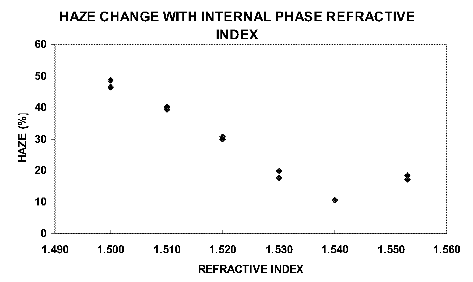
Achieving such tight refractive index matching poses considerable difficulties, because the materials normally used to form capsules walls or binders have considerably higher refractive indices than the fluids normally used in internal phases.

Method used


Image

  • Materials for use in electrophoretic displays
  • Materials for use in electrophoretic displays
  • Materials for use in electrophoretic displays

Examples


example 1

Measurement of Overlap Concentration

[0073] It is known that the concentration of polymer needed to cause stabilization by depletion flocculation in a liquid is related to the overlap concentration of the polymer (i.e., the concentration at which the polymer chains begin to overlap one another). Accordingly, a series of experiments were conducted to determine the overlap concentration of polystyrenes of varying molecular weights in a solvent mixture which can be used as a fluid in electrophoretic media.

[0074] The overlap concentration C* is given by the Mark-Houwink equation:

C*=(KMa)−1

where K is a dimensionless constant. M is the volume average molecular weight in Daltons and a is proportional to the solubility of the polymer in the solvent. Accordingly, C* at any given temperature can be determined by plotting the specific viscosity of a polymer in a liquid against polymer concentration.

[0075] In these experiments, polystyrenes having volume average molecular weights from 382 ...

example 2

Measurement of Optical State Stability

[0077] A series of experimental variable transmission windows were produced using polymer-dispersed polystyrene electrophoretic media of the present invention. These experimental windows used varying concentrations of five different polystyrenes with molecular weights varying from 97 to 983 kD. All the polystyrene samples had narrow polydispersisity with Mw / Mn not greater than 1.3. All electrophoretic media used the same 1.7:1 v / v mixture of Cargille 5040 and Isopar G as in Example 1 above.

[0078] Each window was driven to its maximum transmission optical state, which (it was known empirically) tends to be the least stable state of such media. The optical transmission was measured immediately after the end of the drive pulse and after the medium had been thereafter allowed to stand undriven for one minute; the former transmission is denoted T and the difference between the two values ΔT. FIG. 7 plots the normalized ΔT (i.e., ΔT / T, expressed as ...


PUM

PropertyMeasurementUnit
refractive indexaaaaaaaaaa

Abstract

The image stability of electrophoretic media, comprising a plurality of particles disposed in a fluid and capable of moving through the fluid upon application of an electric field to the medium, can be improved by including in the fluid either a polystyrene or an aggregating diblock copolymer which forms micelle-like structures in the fluid, the diblock copolymer having a first block soluble in the fluid and a second block not swellable by the fluid. In variable transmission electrophoretic media, haze can be reduced by using as the fluid a mixture of a partially hydrogenated aromatic hydrocarbon and a terpene.

Description

REFERENCE TO RELATED APPLICATIONS [0001] This application is a continuation-in-part of copending application Ser. No. 10 / 063,236, filed Apr. 2, 2002 (Publication No. 2002 / 0180687), which claims benefit of Application Ser. No. 60 / 280,951, filed Apr. 2, 2001. This application is also a continuation-in-part of copending application Ser. No. 10 / 711,829, filed Oct. 7, 2004 (Publication No. 2005 / 0168799), which claims benefit of Application Ser. No. 60 / 481,486, filed Oct. 8, 2003; Application Ser. No. 60 / 481,572, filed Oct. 28, 2003; and Application Ser. No. 60 / 481,574, filed Oct. 29, 2003. application Ser. No. 10 / 711,829 is also a continuation-in-part of copending application Ser. No. 10 / 708,130, filed Feb. 9, 2004 (now U.S. Pat. No. 7,002,728), which itself is a continuation-in-part of copending application Ser. No. 10 / 063,803 filed May 15, 2002 (now U.S. Pat. No. 6,822,782), which claims benefit of Application Ser. No. 60 / 291,081, filed May 15, 2001. This application is also a continua...

Claims


Application Information

Patent Timeline
Patent Type & Authority Applications(United States)
IPC IPC(8): G09G3/34G02F1/167
CPCG02F1/167G02F2001/1678E06B2009/2464E06B9/24G02F2203/11G09G3/344
Inventor PAOLINI, RICHARD J. JR.HARRIS, GEORGE G.HONEYMAN, CHARLES HOWIEHERB, CRAIG A.WEBBER, RICHARD M.WHITESIDES, THOMAS H.
Owner E INK CORPORATION
Learn More