Receiving circuit, receiving apparatus, and receiving method

a technology of receiving circuit and receiving apparatus, which is applied in the direction of resonant circuit tuning, pulse automatic control, television systems, etc., can solve the problems of detection circuit erroneously making a determination, and inability to obtain correct video detection output, etc., to achieve stable correct determination, reduce circuit area, and reduce the number of pins

Inactive Publication Date: 2007-06-28
PANASONIC CORP
View PDF7 Cites 16 Cited by
  • Summary
  • Abstract
  • Description
  • Claims
  • Application Information

AI Technical Summary

Benefits of technology

[0041] According to the configuration, the frequency detection circuit can stably correctly make a determination. In an analog comparator in a conventional lock detection circuit, a determination threshold value is affected by a change in temperature, a change in power supply voltage, and fluctuations in divergence of the circuit elements with respect to a reference voltage Vref. In contrast to this, in the frequency detection circuit included in the present invention, since a result indicating that the value falls within the predetermined range is digitally processed, the value is rarely changed depending on a change in temperature, a change in power supply voltage, and fluctuations in divergence of the circuit elements. For this reason, the frequency detection circuit can stably correctly realize the determination.
[0042] The receiving apparatus and the receiving method according to the present invention have the same units as described above and achieve the same effect as described above.
[0043] According to the present invention, even though a video signal is overmodulated, or even though a high-luminance image having a white pattern is used, an erroneous determined can be advantageously predetermined. Furthermore, a smoothing capacitor to determine a locked / unlocked state is made unnecessary, a circuit area can be reduced, or the number of pins which connect an external capacitor can be advantageously prevented from increasing. Furthermore, the frequency detection circuit is also used as a counter for the digital AFT device to make it possible to further reduce the circuit area.

Problems solved by technology

As a problem (1), a lock detection circuit erroneously makes a determination when a VIF signal is overmodulated disadvantageously.
As a result, a correct video detection output cannot be obtained (signal C′ in FIG. 5).
As a problem (2), even though the VIF signal has a normal degree of modulation (87.5%), the lock detection circuit erroneously makes a determination due to a video pattern.
For this reason, when the reference voltage Vref is set at a low level in consideration of these conditions, a locked state is easily erroneously determined in an unlocked state.
In any case, an increase in cost is caused.

Method used


Image

  • Receiving circuit, receiving apparatus, and receiving method
  • Receiving circuit, receiving apparatus, and receiving method
  • Receiving circuit, receiving apparatus, and receiving method

Examples


Embodiment Construction

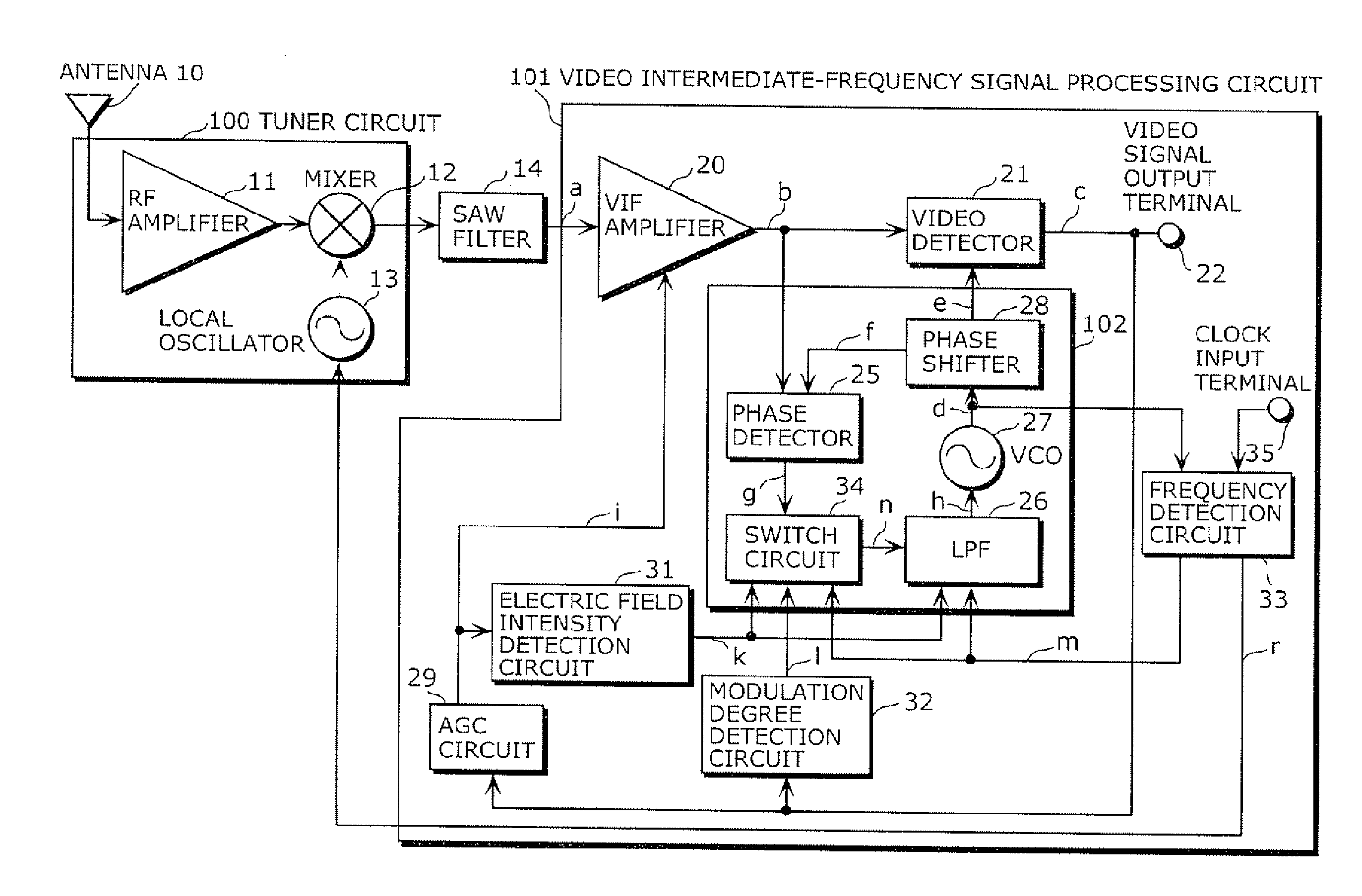
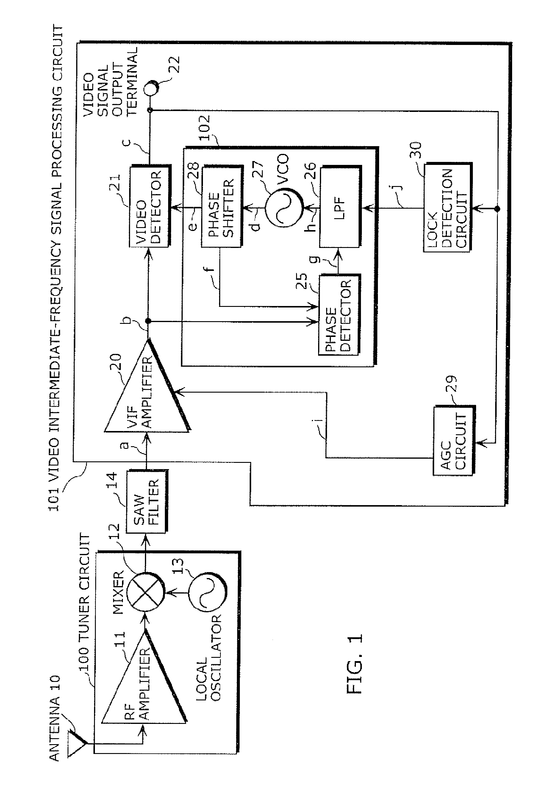
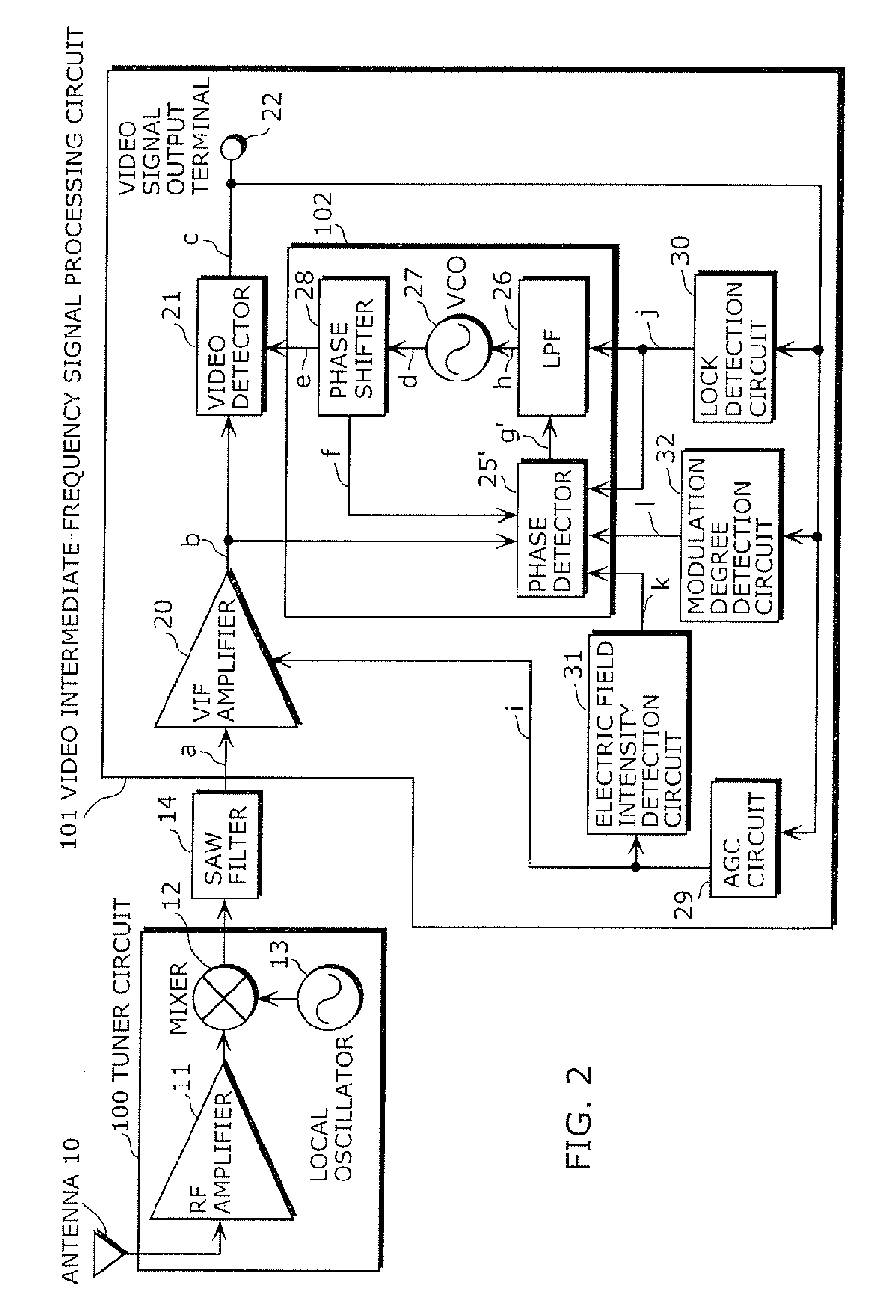
[0058] In a video intermediate-frequency signal processing circuit according to this embodiment, a determination of a locked / unlocked state of a PLL circuit 102 is performed based on an oscillation output d from a VCO 27 but a video detection output c. More specifically, it is determined whether a frequency of the oscillation output d from the VCO 27 falls within a range which is allowed as a video intermediate frequency. In this manner, even though a video signal is overmodulated, or even though a high-luminance image having a white pattern is used, an erroneous determination can be prevented, and a capacitor to smooth the video signal is made unnecessary. For this reason, a circuit area can be reduced.

[0059] An embodiment of the present invention will be described below with reference to the accompanying drawings.

[0060]FIG. 6 is a block diagram showing a receiving apparatus including a video intermediate-frequency signal processing circuit according to an embodiment of the prese...


PUM


Abstract

A receiving circuit according to the present invention includes a phase-locked loop circuit which outputs an oscillation signal synchronized with a phase of a modulation signal modulated by a video signal, a video signal detector which synchronously detects the modulation signal using the oscillation signal, so as to output the video signal, and a frequency detection circuit which determines whether the frequency of the oscillation signal falls within a predetermined range, so as to output a frequency detection signal indicating whether the phase-locked loop circuit is in a locked state. The receiving circuit controls the phaselocked loop circuit using the frequency detection signal

Description

BACKGROUND OF THE INVENTION [0001] (1) Field of the Invention [0002] The present invention relates to a circuit which processes a video intermediate-frequency signal using a phase-locked loop (to be referred to as a PLL hereinafter), and particularly to a receiving circuit which can obtain a stable video detection output even when an input signal is in an overmodulated state. For example, the receiving circuit is used in a field of a television receiver and a video player having a television tuner built therein. [0003] (2) Description of the Related Art [0004] For example, in an intermediate-frequency stage of a television set or the like, a synchronous detection circuit is used to detect an amplitude modulation wave (for example, Laid-Open Japanese Patent Application No. 03-44280 and Japanese Laid-Open Patent Application No. 05-244533). FIG. 1 is a block diagram showing a receiving apparatus including a video intermediate-frequency signal processing circuit of a conventional PLL sy...

Claims


Application Information

Patent Timeline
Patent Type & Authority Applications(United States)
IPC IPC(8): H04N5/50H04N5/44
CPCH03J1/0041H03L7/10H04N5/455H04N5/50H04N21/4383H03L7/113
Inventor MORI, SACHIKOOBA, YASUOIKUMA, MAKOTO
Owner PANASONIC CORP
Why Eureka
Try Eureka