Color filter device

a filter device and color technology, applied in the field of color filter devices, can solve the problems of high cost of white light emitting diodes, achieve the effects of reducing fabrication costs, increasing intensity, and improving light transformation efficiency

Inactive Publication Date: 2007-06-28
WINTEK CORP
View PDF10 Cites 35 Cited by
  • Summary
  • Abstract
  • Description
  • Claims
  • Application Information

AI Technical Summary

Benefits of technology

[0006]Hence, an object of the invention is to provide a color filter device capable of coupling with a backlight source with a short wavelength in a display for not only increasing the intensity and the color temperature of transmission light in a color display to improve light transformation efficiency but also lowering the fabrication cost.
[0008]Through the design of the invention, by integrating a phosphor layer into the color filter device, a low cost LED with a short wavelength (10 nm-490 nm), such as a blue LED or an ultraviolet LED, can be used as a backlight source instead of an expensive white LED without the need of additional manufacturing processes and facilities. Therefore, the design of the invention not only lowers the fabrication cost of a backlight module but also increases the intensity and the color temperature of transmission light in a color display due to the short-wavelength LED so as to improve the light transformation efficiency.

Problems solved by technology

However, the cost of the white light emitting diode is high.

Method used


Image

  • Color filter device
  • Color filter device
  • Color filter device

Examples


Embodiment Construction

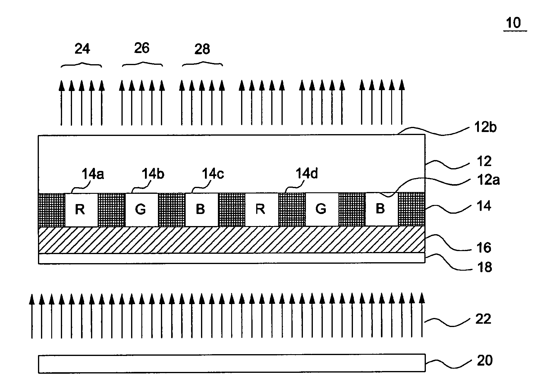
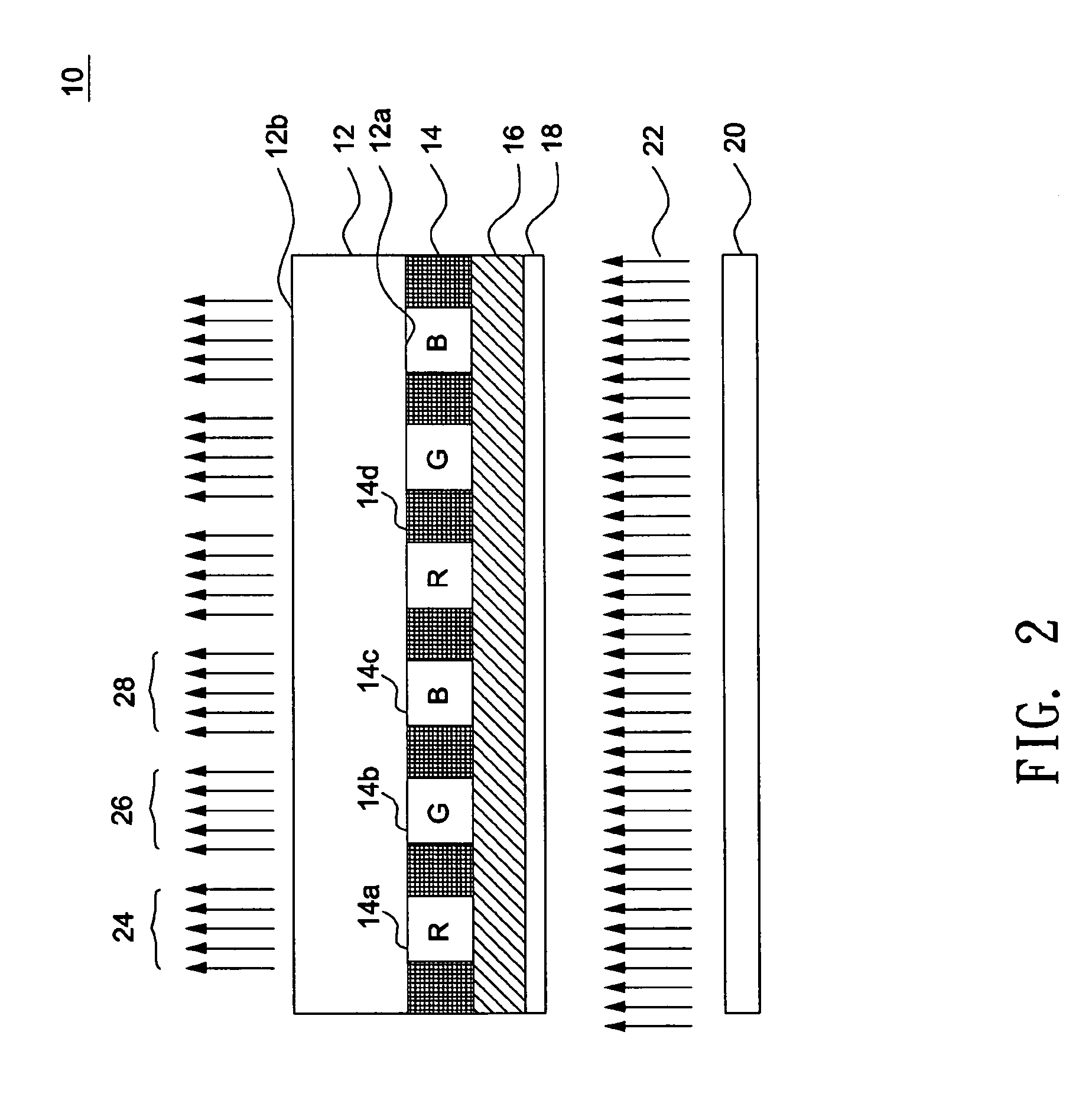
[0023]FIG. 2 shows a schematic diagram illustrating a color filter device 10 according to an embodiment of the invention. As shown in FIG. 2, the color filter device 10 includes a transparent substrate 12, a color filter layer 14, a phosphor layer 16, and an overcoat layer 18. The transparent substrate 12 is a glass substrate and has a light-receiving surface 12a facing a backlight module 20 and a light-transmitting surface 12b opposite to the light-receiving surface 12a. According to this embodiment, the color filter layer 14, the phosphor layer 16, and the overcoat layer 18 are provided sequentially on the light-receiving surface 12a of the transparent substrate 12. Note that, as used in the specification and the appended claims, the meaning of the phrase “layer A is provided on layer B” is not limited to a direct contact between the upper layer A and the lower layer B. For instance, in an embodiment where laminates are interposed between the upper layer A and the lower layer B is...


PUM

PropertyMeasurementUnit
wavelengthaaaaaaaaaa

Abstract

A color filter device includes a transparent substrate, a phosphor layer, and a color filter layer. The phosphor layer is provided on the transparent substrate to transform incoming light having a short wavelength into white light having a broad range of wavelengths. The color filter layer is provided on the transparent substrate and has multiple filter sections for filtering the white light to generate desired light components of primary colors.

Description

BACKGROUND OF THE INVENTION[0001](a) Field of the Invention[0002]The invention relates to a color filter device, and particularly to a color filter device for a display using a short-wavelength (10 nm-490 nm) light source as its backlight source.[0003](b) Description of the Related Art[0004]FIG. 1 shows a schematic diagram illustrating a conventional color filter device. As shown in FIG. 1, the conventional color filter device 100 includes a glass substrate 102, a color filter layer 104, and an overcoat layer 106, where the color filter layer 104 and the overcoat layer 106 are sequentially provided on the glass substrate 102. The color filter layer 104 includes a red filter section 104a, a green filter section 104b, a blue filter section 104c, and a black matrix 104d provided between two neighboring filter sections for shielding light in the peripheries of sub-pixels. Each of the filter sections is distinguished by a different color of an organic pigment. When white light 108 transm...

Claims


Application Information

Patent Timeline
Patent Type & Authority Applications(United States)
IPC IPC(8): G02F1/1335
CPCG02B5/201G02B5/223G02F1/133514G02F1/133617G02F2001/133614G02F1/133614
Inventor WANG, CHIH-YUANCHANG, HUI-YULEE, YI-TE
Owner WINTEK CORP
Why Eureka
Try Eureka